How to Build an Infrared Detector Circuit
In this project, we will build an infrared detector circuit using an infrared LED and an IR phototransistor.
The 2 electronic components work as a pair. One emits the infrared light (the IR LED) and the other detects the infrared light (the IR phototransistor).
An infrared LED is an LED that creates and beams out infrared light. Being that our circuit is made to detect infrared, we need the IR LED to be a source of infrared so that we can test our detector out.
An IR phototransistor is a transistor that detects infrared light. Only with infrared light will the phototransistor turn on and be in conduction mode. Without infrared and the phototransistor will not conduct across from collector to emitter. Therefore, if a load is connected to the output of the phototransistor, it will turn on if infrared is detected, and it will be off with infrared isn't detected.
Being that an IR phototransistor only reacts to infrared, it is perfect to be used for infrared detector circuits, which is one of the most used applications for it.
How the circuit works is very basic. An IR LED will beam infrared rays of light and the phototransistor, made up of infrared-light sensitive material, responds to this infrared light and conducts. Therefore, if an output is connected to the phototransistor, it will turn on when the infrared LED is beaming unimpeded on the phototransistor, and it will be off when the IR LED is not beaming on it.
Infrared LEDs and phototransistors are rated based on the wavelength of the infrared light. Therefore, a 940nm infrared LED must
be matched up with a phototransistor that detects 940nm wavelength. They have to be matching pair in order to work. Therefore, in our circuit,
we will use a 940nm IR LED and a matching 940nm phototransistor.
Components
- 940nm IR LED
- 940nm IR phototransistor
- 2 470Ω resistors
- LED
The phototransistor and IR LEDs can be found from a number of online retailers, including ebay and taydaelectronics.
The type we will use is the common 940nm infrared LED and phototransistor combination. But, in actuality, you could use any wavelength; again as long as it's a matching pair between the IR LED and phototransistor, it wil work. So feel free to use others.
IR Phototransistor Detector Circuit
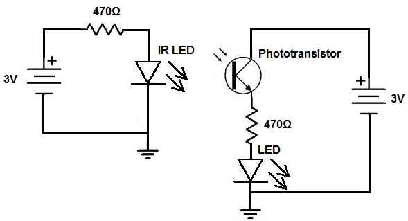
The infrared (IR) detector circuit we will build with an IR phototransistor is shown below.
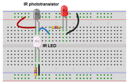
This above circuit built on a breadboard is shown below.
How this circuit works is once there is that once there is an infrared light of the specific wavelength that the IR phototransistor is made to detect, the load connected to the phototransistor will turn on. So when the IR LED circuit is on and the IR flashes infrared on it, the red output LED will light up in the circuit.
If the IR LED is not on and beaming at the phototransistor, the phototransistor will not conduct across from collector to emitter Therefore, the red output LED will be off.
So this is a classic example of a infrared detector circuit. When infrared is detected, the output, in this case, an LED is powered on.
Related Resources
How to Build a Dark-activated Switch