
How to Build a Inverting Op Amp Circuit
In this project, we will show how to build an inverting op amp circuit using an LM741 op amp chip.
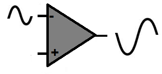
This is a circuit in which the polarity of the signal at the output will be inverted or flipped from the signal going into the input.
It is as if the signals on the output get flipped vertically.
The opposite of this is a non-inverting op amp circuit, in which the polarity of the output signal is the same as the input signal.
This circuit will be very basic. It will illustrate all that needs to be known for connecting the inverting terminal
up for input.
Components Needed
- LM741 Op Amp Chip
- 1KΩ resistor
- 10KΩ resistor
- AC Signal Source
The LM741 is a widely used and available chip in the electronics world. It can be obtained from many different online electronics retailers.
It is composed of a single op amp which serves as a general purpose amplifier.
The chip is an 8-pin chip. Its pinout is shown below.
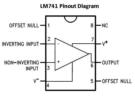
The pins we are going to connect are pins 2, 3, 4, 6, and 7. Pins 1, 5, and 8 will be left unconnected.
For the LM741 to work, it needs power. The LM741 is a dual power supply op amp. This means it needs 2 sources of power. It needs positive voltage at pin 7 and negative voltage at pin 4.
The remaining 3 pins are the 2 inputs and 1 output of the op amp. Of the 2 input pins, one pin is the inverting input and the other is the noninverting input.
To learn in more thorough detail the pinout of the LM741, see LM741 Pinout Connections.
For this circuit, we will input an AC (alternating current) signal into the op amp, which serves as our input signal. A great source for AC signals is a function generator. A function generator can generate perfect sine wave signals. These are easy to see on an oscilloscope. So if you have a function generator, you can use a signal from it as the input signal for the circuit.
Also, if you have an oscilloscope, this can be used to visually see and measure the input signal going into the op amp and the output signal going out.
All this is described below.
Inverting Op Amp Circuit
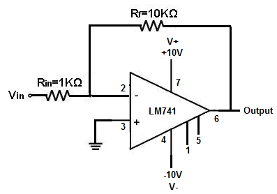
The op amp circuit which produces an inverted output signal is shown below.
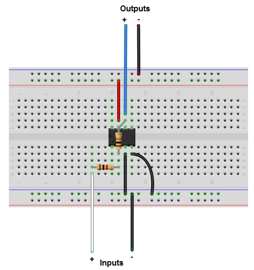
The breadboard schematic version of the above circuit is shown below.
In this circuit, we use the inverting terminal of the op amp as our signal input source. This is where you will place the incoming input signal.
Even though this circuit is made so that it illustrates mainly inverting output signals, it is made so that it gives out an inverting signal with a gain. This circuit above provides a gain of about 10. This means the voltage output will be 10 times greater than the voltage input.
This is because the formula for inverting op amp gain is:
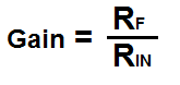
Since we're using a 10KΩ resistor and a 1KΩ resistor, this gives a gain of 10KΩ/1KΩ= 10.
If you want to adjust the gain, then you can just swap out resistors.
To test this circuit out, place a sine wave signal at the inverting terminal of the op amp. The same signal
should appear on the output only with opposite polarity.
Related Resources
How to Build a Non-inverting Op Amp Circuit