
LM317 Voltage Regulator
The LM317 Voltage Regulator is a 3-terminal
adjustable voltage
regulator which can supply an output voltage adjustable from 1.2V to 37V. It can supply more than 1.5A of load current to
a load.
LM317 Pinout
LM317 Schematic Diagram
LM317 Circuit
LM317 Datasheet
LM317 Pinout
The LM317 Voltage Regulator has 3 pins. Below is the pinout:
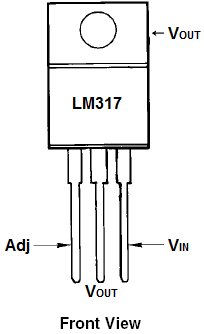
Looking from the front of the voltage regulator, the first pin (on the left) is the Adjustable Pin, the middle is Vout, and the last pin(on the right) is VIN.
VIN- VIN is the pin which receives the incoming voltage which is to be regulated down to a specified voltage. For example,
the input voltage pin can be fed 12V, which the regulator will regulate down to 10V. The input pin receives the incoming, unregulated voltage.
Adjustable- The Adjustable pin (Adj) is the pin which allows for adjustable voltage output. To adjust output, we swap out resistor R2 value for a different
resistance. This creates adjustable voltages.
VOUT- VOUT is the pin which outputs the regulated voltage. For example, the LM317 may receive 12V as the input and output
a constant 10V as output.
LM317 Schematic Diagram
Now that you know the pins, how do we modify the voltage to that which we want output?
We do this by changing the value of the resistor connected to the Adj pin of the voltage regulator.
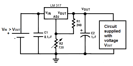
Let's see how the schematic is set up:

Here you see we connect two resistors to the voltage regulator. These resistors determine the voltage that the voltage regulator adjusts to and outputs.
The voltage that the adjustable regulator outputs is determined by the equation below:
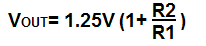
Therefore, you can see based on this formula, that the more the value of resistor R2 increases, the greater the voltage output.
In our setup now, these are the values we're going to use. We're going to put 12 volts into the voltage regulator and regulate it down to 5V. Based on the formula above, in order for the LM317 to output 5 volts, the value of R2 must be 720Ω. Set this above circuit up and then use a multimeter to check the output voltage by placing it across the 1µF capacitor or across the the resistors. You will discover it's very close to 5 volts. Now swap out the R2 resistor and place a 1.5KΩ resistor in its place. Now the voltage output should be near 10V.
This is the advantage of adjustable voltage regulators. You can adjust it to any voltage within the range that the voltage regulator supports.
Note: The capacitors C1 and C2 are used to clean up the power line. C1 is optional and it's used to clean up transient response.
C2 is needed if the device is far from any filter capacitors. This capacitors helps smooth out the power supply line in case of abrupt current spikes.
LM317 Circuit
This is how a LM317 regulator would look when connected to a circuit so that it supplies a constant DC voltage output.
In this circuit, we add a DC voltage supply to the VIN pin of the regulator. This is the pin which, again, receives incoming voltage which the chip will then regulate down. The voltage which enters this pin must be larger than the voltage it is feeding out. Remember, voltage regulators are just devices that regulate voltage down to a certain level. They do not and cannot create voltage on their own. Therefore, in order to a get a voltage, VOUT, VIN must be greater than VOUT. In this circuit, we want a regulated 5VDC as output. Therefore, VIN must be greater than 5 volts. Generally, with regulators, unless they are low drop out regulators, you want the input voltage to be about 2 volts higher. So therefore, since we want 5 volts as output, we will feed into this regulator 7 volts.
Now that we've dealt with the input pin, we must now deal with the adjustable pin (Adj). This is the pin which allows us to adjust the voltage to the level we want. Since we want 5 volts to be output, we must calculate which value of R2 will yield an output of 5 volts. Using the formula for the output voltage, VOUT= 1.25V (1 + R2/R1). Being that R1=240Ω, our equation is now 5V= 1.25V (1 + R2/240Ω), so R2=720Ω. So with R2 being a value of 720Ω, the LM317 will output 5V if fed an input voltage greater than 5 volts. If you need to calculate output voltages or which resistor R2 value you would need for a circuit, see our LM317 Resistor and Voltage Calculator. This can help you find the exact resistor value needed for a circuit.
The last pin of the LM317 is the output pin. This is where the regulated voltage (in this case, 5 volts) will come out. To feed a circuit the regulated
5 volts, we just connect it to the output pin.
LM317 Datasheet
The datasheet for a LM317 goes much more depth than this article, which was only created to serve as a beginner's guide to this voltage regulator. To find
out more details about it, see the datasheet which is attached below:
LM317 Datasheet