
How to Build a Low Battery LED Warning Circuit

In this circuit, we build a low battery LED warning circuit.
This is a common circuit where an LED (typically a red LED) lights up when the battery is running low in order to alert the user that the battery will soon die and should be recharged.
This is good because it gives the user a warning and time to recharge before the device totally goes dead and most users appreciate this. Not to mention implementing this LED can be done very cheaply. A comparator along with the resistors and LED needed can all be gotten for less than $1. The circuit that is constructed here below on this page is less than $1 in cost. Therefore, it offers a very useful function while not adding much cost to a device.
Implementing a simple LED low battery warning system is much cheaper than an LCD system, as an LCD is much more expensive than an LCD and not to mention that it takes up much more space. Also, if you have a system that tells you the exact percentage of battery charge remaining, such as what you see on a standard smartphone today such as an iphone, this adds enormous cost to a device (dollars), because you would need a microprocessor/microcontroller along with a fuel gauge IC and LCD to make it work. For simple systems, where it is important to keep the price low and where real estate space on the device may be very limited, this wouldn't be the way to take. A simple LED system is sufficient in that case.
So let's see how we can create a low battery LED warning system using a basic comparator IC, along with a zener diode, a few resistors and an LED.
You can pretty much use any comparator IC. In this case, we use the LM311 comparator IC.
This circuit exploits how comparators work in that they compare voltages and outputs a logic HIGH value to the output when the voltage at the inverting terminal is higher than at the noninverting terminal.
We take the approach that we feed a fixed reference voltage of 2.4V to the inverting terminal of the op amp. This reference voltage can be any level you want. It can be 2V. It can be 3V. How you choose the reference voltage depends on the nominal voltage you choose for the zener diode. We use a zener diode in our circuit to set the low battery voltage warning level. We cannot use a resistor voltage divider, because the battery voltage cannot be fixed in a case like that, because the voltage of a battery system is always changing. When the battery is being used without being recharged, it is decreasing. When the battery is being recharged, the voltage is increasing. Thus, the only way to have a set reference voltage level is to use a component such as a zener diode that maintains a fixed voltage level despite a changing power supply level feeding it. In this circuit, we opt to use 2.4V, but zener diodes come in many different nominal voltage levels, and you can choose what suits your circuit.
So our reference voltage will be 2.4V, but as stated above, you can always change this to suit your particular needs.
We feed this reference voltage into the inverting input terminal.
Into the noninverting input is input the mains power of our device, or the battery of the device.
As long as the battery voltage is above the reference voltage, in this case, 2.4V, the LED will be off.
Once the battery goes below the reference voltage (or the inverting terminal voltage goes above the noninverting terminal voltage), then the LED turns on.
Components Needed
- LM311 Comparator Chip
- 2.4V zener diode
- 1KΩ resistor
- LED
- 220Ω resistor
So all we need is the LM311 comparator chip and 4 external components, which includes the zener diode, the LED and 2 resistors.
The circuit that we will build that allows us to detect when the battery voltage goes below 2.4V is shown below.
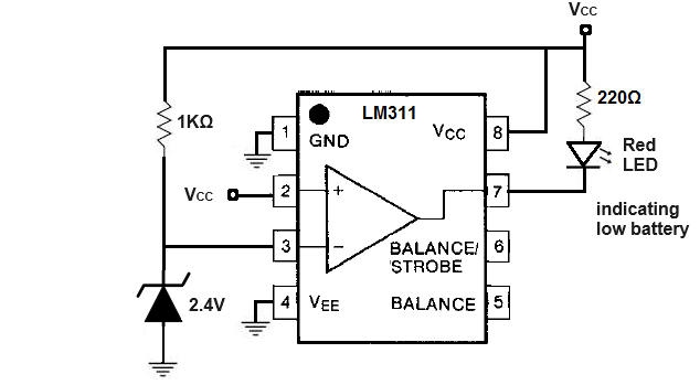
Pin 1 is GND and, thus, gets connected to the ground of the power source.
Pin 8 is where you connect the positive terminal of the power source. In this case, we are working with 5V.
Pin 4 gets grounded, because we use collector output instead of emitter output.
Pins 5 and 6 are left unconnected.
The remaining 3 pins are the op amp terminals.
Pin 2 is the noninverting op amp input pin. To this pin, we connect the device's power to. This pin connects to VCC, which represents the power source of the electronic device.
Pin 3 is the inverting op amp input pin. This is the pin where we set our reference voltage to. This is the voltage that doesn't change. In this case, we set it to 2.4V, the nominal voltage for which our zener diode is rated for. A resistor must be placed along with this zener diode, because any voltage in excess of the zener diode must be dropped across a resistor. In our case, we use a 1KΩ resistor.
Pin 7 is the output of the op amp. The output of the amp will go to a HIGH logic state when the voltage at the inverting terminal is greater than at the noninverting terminal.
How this circuit works is that, let's imagine the battery is fully charged on the electronic device at 5V.
In this case, the noninverting input terminal voltage is much greater than the inverting input terminal voltage and, thus, the output is LOW and the LED is off. At the beginning, the noninverting input voltage is 5V, while the inverting input voltage is 2.4V.
As the battery is used, its voltage decreases and decreases. 5V eventually becomes 4.5V, 4V, 3.5V, etc.
Once the voltage goes below the reference voltage of 2.4V at the inverting terminal, then the output goes HIGH and the red LED turns on.
This now warns the user of a low battery warning.
Again, you can set the reference voltage to any voltage less than the nominal voltage. It can be 3.5V, 3V, 2V, 1.5V. You would just have to choose the correctly rated zener diode.
You should choose the voltage somewhat above the voltage where the circuit would stop having sufficient power to function.
And this is a basic circuit that can function as a low battery LED warning circuit.
It's a very low-cost, effective solution which provides useful information about the battery to a user without adding much more cost to a device.
Related Resources