How to Build a Dual Digital Potentiometer Circuit Using a MCP4231
In this project, we are going to show how to connect a dual digital potentiometer chip to a microcontroller so that we can control 2 potentiometers so that we can vary the resistance delivered to 2 different output devices.
A dual digital potentiometer chip is a chip which contains 2 potentiometers. This means we have 2 potentiometers to work with instead of just one. Therefore, we can connect 2 different output devices to this chip and have different resistances delivered to them.
Just like a regular potentiometer, a digital Pot IC comes in all different values of resistance.
The specific digital potentiometer we will use in this circuit is the MCP4231 IC. The MCP line of potentiometers come in 5KΩ, 10KΩ, 50KΩ, and 100KΩ, meaning you can purchase the IC in any of these maximum resistance values.
We will connect this digital pot IC to the arduino microcontroller. Through software, we will then be able to change the resistance output at the wiper terminals of the potentiometers.
In this circuit, we will use 2 different color LEDs as our output devices. Let's say we will use a red LED as our first LED and a green LED as our second LED. For one LED, we can start it off at the highest resistance (when the LED will be off), while the other LED will be started at the lowest resistance (when the LED will be the brightest). We will then increase the brightness of the red LED, while dimming the green LED. And we'll continually rotate this.
This circuit will help to demonstrate how a dual potentiometer IC works
to control output devices.
Components
- MCP4231 Digital Potentiometer
- 2 1.2Ω resistor
- Red Ultra low-current LED
- Green Ultra low-current LED
- Arduino microcontroller
The MCP4231 is a dual digital potentiometer chip.
By dual, it's meant that the chip contains 2 potentiometers. A single potentiometer IC such as the MCP4131 contains one potentiometer. A dual IC contains 2. These potentiomters are completely separate and independent of each other, so that one doesn't affect the other.
You can download the datasheet of the MCP4231 at the following link: MCP4231 Datasheet.
The MCP4231 operates on anywhere from 1.8V to 5.5V. Since the arduino provides 5V of power, it provides a perfect power source for the MCP4231 IC.
The MCP4231 changes resistance in either 129 steps, from 0 to 128, or 256 steps, from 0 to 255. However, we will use in this circuit 129 steps for a complete revolution. Thus, with a 100KΩ resistor, each step is an increment of approximately 775Ω (100K/129≈775Ω). With a 10KΩ resistor, each step is an increment of approximately 78Ω.
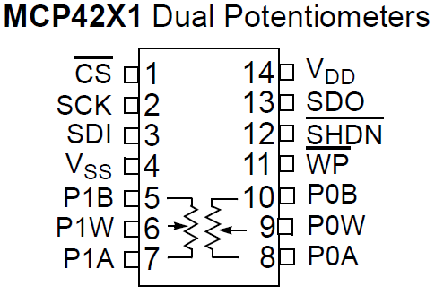
The MCP4231 is a 14-pin IC.
Its pinout is shown below.
The table below summarizes the pins of the IC.
| MCP4231 Digital Potentiometer | ||
| Pin # | Pin Name | Description |
| 1 | CS | The CS, or Chip Select, pin is the SS (slave select) pin for the SPI interface. It is active low. 0V means the chip is selected and 5V means it is not selected. |
| 2 | SCLK | SCLK is the Shared/Serial Clock. It is the SPI clock line. |
| 3 | SDI | These pins are the serial data in, also known as the MOSI. |
| 4 | VSS | This is where ground is connected to. |
| 5 | P1B | This is one terminal of potentiometer 1. |
| 6 | P1W | This is the wiper terminal of potentiometer 1. |
| 7 | P1A | This is one terminal of potentiometer 1. |
| 8 | PA0 | This is one terminal of potentiometer 0. |
| 9 | PW0 | This is the wiper terminal of potentiometer 0. |
| 10 | PB0 | This is one terminal of potentiometer 0. |
| 11 | WP | This is Write Protect. You can ignore this pin. It's left not connected (NC). |
| 12 | SHDN | This is the Shutdown pin. It is active low. When held low, the hardware disconnects the wiper fro the internal resistor network. Since we always want the potentiometer ot be active, we keep this pin connected to +5V. |
| 13 | SDO | This is the serial data output pin. This pin is also known as MISO. |
| 14 | VDD | This is where the positive voltage source connects to. |
The MCP4231 digital potentiometer communicates via the Serial Peripheral Interface bus, or SPI bus.
Other ways of communicating are through the I2C bus and the serial UART bus.
The SPI us was originally created by Motorola and is a full-duplex serial communication standard that enables simultaneous bidirectional communication between a master device and one or more slave devices. Many times, SPI devices connect to one another, so that there is a master SPI and then slave SPI devices which communicate in sync with each other.
With the SPI, unlike the I2C bus, the SPI bus uses separate lines for sending and receiving data, and it employs an additional line for selecting which slave device you are talking to. This adds additional wires, but also eliminates needing different slave device addresses (since it's hardware connected instead of through software). SPI runs at a faster speed than I2C and generally easier for beginners to work with.
SPI devices are synchronous, meaning that data is transmitted in sync with a shared clock signal (SCLK). Data can be shifted into the slave device on either the rising or the falling edge of the clock signal.
The Arduino has SPI support, containing a built-in library and hardware to communicate with a digitally controllable potentiometer.
The Chip Select pin decides which slave device you are communicating to. The Chip Select pin is also known
as the Slave Select (SS) pin. If you just have one slave device,
the chip select pin of that slave device has to drawn LOW to communicate with it, since the CS pin is an active low pin. After you are done
communicating with the device, the CS pin should then be drawn HIGH.
MCP4231 Dual Digital Potentiometer Circuit
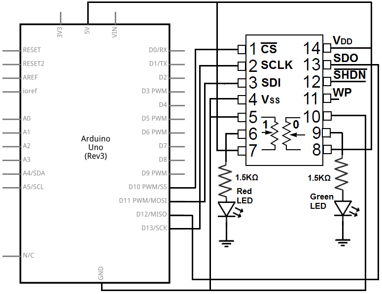
The MCP4231 digital potentiometer circuit that we will build to control the brightness of 2 ultra low-current LEDs, alternating between the 2 so that one is fully bright while the other is off, is shown below.
The LEDs must be low-current, because the maximum current that can pass through any of the potentiometer terminals is 2.5mA.
Since the power we are working with does not exceed 2.5mA, we do not exceed the specifications of the chip.
Our power is 5V-1.65V/1.5KΩ= 0.00223A or 2.23mA.
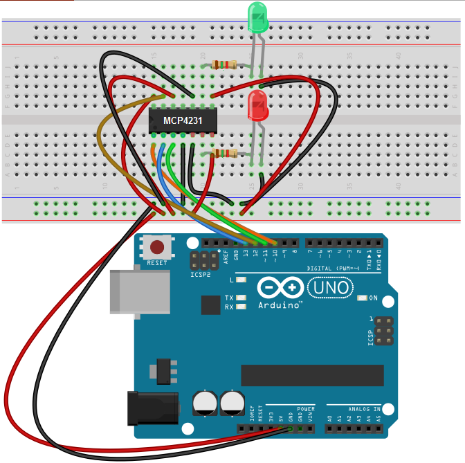
This above circuit built on a breadboard is shown below.
In this circuit, we connect pin 1, the
We connect pin 2, SCK, to digital pin 13 on the arduino.
We connect pin 3, SDI, to digital pin 11 on the arduino.
We connect pin 4, GND, to the ground terminal on the arduino.
We connect pin 5, P1B, to ground.
We connect pin 6, P1W, the wiper terminal of potentiometer 1, to the output device that we want to turn on. In the case of this circuit, it is the red LED which is in series with a current-limiting resistor. Being that the wiper terminal attaches to this LED, we can adjust the resistance, through software, to display different brightnesses of the LED.
We connect, Pin 7, P1A, to +5V. So one of the terminals of the potentiometer are connected to ground and the other is connected to +5V.
We connect pin 8, P0A, to the +5V terminal on the arduino.
We connect pin 9, P0W, the wiper terminal of potentiometer 0 to the green LED through a series-limiting resistor.
We connect pin 10, P0B, to ground.
We leave pin 11, WP, unconnected. On the datasheet, it really is a Not Connect (NC) pin.
We connect pin 12,
We connect pin 13, SDO, to digital pin 12 on the arduino.
We connect pin 14, VDD, to the +5V terminal on the arduino.
Code
The code so that we can run the full range of resistances from the
potentiometers to alternate the brightening and dimming of our LEDs is shown below.
#include <SPI.h>
byte addressRedLED = B00010000;
byte addressGreenLED = B00000000;
int CS= 10;
void setup()
{
pinMode (CS, OUTPUT);
SPI.begin();
}
void loop()
{
for (int i = 0; i <= 128; i++)
{
int j=128-i;
digitalPotWriteRed(i);
digitalPotWriteGreen(j);
delay(10);
}
delay(2000);
for (int i = 128; i >= 0; i--)
{
int j= 128-i;
digitalPotWriteRed(i);
digitalPotWriteGreen(j);
delay(10);
}
}
int digitalPotWriteRed(int valueRed)
{
digitalWrite(CS, LOW);
SPI.transfer(addressRedLED);
SPI.transfer(valueRed);
digitalWrite(CS, HIGH);
}
int digitalPotWriteGreen(int valueGreen)
{
digitalWrite(CS, LOW);
SPI.transfer(addressGreenLED);
SPI.transfer(valueGreen);
digitalWrite(CS, HIGH);
}
The first thing is we include the SPI.h library. You shouldn't have to download this. It should automatically
come with the arduino software. You just have to import the library. Then you should see the line, #include We then initialize 2 variables. These are address and CS. The Address variables holds a register value. An SPI device
uses registers to know the address of the register and command to perform on a particular register. The MCP4231 command byte is AD3 AD2 AD1 AD0 C1 C0 D9 D8.
AD3-AD0 is the address of the register on which you would like to perform a command. The address of the wiper terminal of the potentiometer 1
is 0001. The address of the wiper terminal of potentiometer 0 is 0000. Based on these addresses, we can write data to these wiper terminals
to change the resistance value of the potentiometer. So it's the most important address. C1 C0 is one
of 4 possible commands that can be sent to the address we've chosen. We can either read data from the address, write data to the address,
increment the data of the wiper by a value of 1, or decrement the data by a value of 1. The command for writing data to the address is 00.
Since we want to write data to the wiper terminal
(in order to change the resistance), we use 00 (write command). D9 D8 refers the data bits. D9 is undefined and
is always 0. D8 refers to the total number of steps in one complete revolution. For 257-step potentiometers, D8 is used to have the full
resistance scale. Otherwise, it should be 0. We keep ours as 00.
So the final register value of the red LED is 00010000. The final register value for the green LED is
00000000.
So the chip select pin is connected to digital pin 10 on the arduino, so we initalize the CS variable to 10.
In the setup() function, we set the CS as output. We then call the SPI.begin() function, which creates all the proper
initialization so that the SPI can get up and running.
In our loop() function, we call a for loop that goes from 0 to 128, corresponding to the number of steps in a complete
revolution of the potentiometer. We call the digitalPotWriteRed() function in this for loop to pass the i value to the wiper terminal 1 connected to the red LED. The first
for loop counts from 0 to 128. So during this sequence, the red LED is on at first and then becomes dimmer and dimmer. Meanwhile, we created a j variable that really is on the opposite
end of the spectrum of values. When i=128, j=0. We place this j value into the wiper terminal of potentiometer 0. So when the red LED is on initially, the green LED is off.
Later as the red LED gets dimmer and dimmer, the green LED gets brighter and brighter.
The second
for loop counts from 128 down to 0. So the red LED during this sequence goes from being off to becoming progressively dimmer. The green LED, on the other hand, gets progressively brighter.
In between
these 2 sequences is a 2-second delay. You can adjust this time period if you want.
The digitalPotWriteRed() function and the digitalPotWriteGreen() function is the last block of code. In this function, we select the MCP4231 digital potentiometer chip by
drawing the CS pin LOW. This is how we select the device, so the MCP4231 is now selected. After this, we call the address that we want to
write to. Above, we initialized the red LED address variable to 00010000; this selects the wiper terminal of potentiometer 1 which we will write to.
We then transfer the value which is taken from the i in the for loop to the wiper terminal. This changes its resistance. Lastly, we draw
the CS pin HIGH, ending the communication with the MCP4231. Whenever we write to a slave device, we draw the CS LOW. Afterwards, when we're
finished with the function, we draw the CS HIGH, to unselect it. Typically, if you only have one SPI slave device, it wouldn't be necessary
to do this. But it's good practice, hence, we show it here. But if you have multiple SPI devices you are communicating with, you would have
to draw the CS pin HIGH. This is because you can only communicate with one device at a time. Therefore, you would have to draw the CS pin HIGH
after communicating with a device.
We do the same exact thing for the digitalPotWriteGreen() function. Except in this case, the address is 00000000. Everything else is identical.
Related Resources
How to Build a Digital Potentiometer Circuit Using a MCP4131