
How to Create a Motion Detector Circuit with a STM32F407G Discovery Board in C

In this article, we go over how to create a motion detector circuit with an STM32F407G discovery board in C.
This enables us to be able to detect motion in front of the sensor, for example, if an object passes in front of it.
The type of motion detector sensor we will use is an infrared distance sensor, shown below.

Depending on the specific type you buy, it may be powered by either 3-5V or 12-15V or have an adjustable detection range of 0-80cm or 0-200cm.
Make sure that you get the infrared sensor powered by 3-5V because this is what the STM32F407G board supplies.
The adjustable range is up to you. 0-200cm can sense farther range, but it depends on your need. 0-80cm may be sufficient.
This is a solid sensor that allows us to detect whether an object passes in front of it.
The infrared sensor has 3 electrical pins, 2 are for power, VDD and GND. The last is the signal pin that outputs a voltage.
Read the datasheet of the infrared sensor that you purchase to find out what signal the sensor sends out when without obstacles and with obstacles.
The type that I use personally in this project sends out a 0 when there are no obstacles in front of it and sends out a 1 when there are obstacles in front of it. This is important when we are coding our software.
So when motion is detected, we have a buzzer connected to output that will buzz for 10 seconds.
The circuit we will build is shown below.
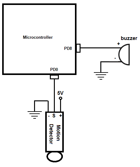
So we will use 2 I/O pins for connections to our electrical devices, the motion sensor and the buzzer.
So now that we have the hardware configuration, next we need the software that will sound the buzzer when motion is detected by the infrared distance sensor.
So below we show the code how to read the signal from the motion sensor and sound a buzzer for 10 second when motion is
detected by the sensor.
We now will explain the code.
We first create a delay function, which we will use later in our code in order to add a delay in order to make the buzzer sound for a specified period of time. We don't want the buzzer sounding for a millisecond. We want the buzzer to go off for a good period of time so that we are alerted that motion was detected.
Next, we define our peripheral registers.
These are the registers we must use during our program.
The first register is GPIO port D register, represented by the variable, pGPIODModeReg
If you look this up in the memory map of the datasheet for the STM32F407G discovery board, this port has a base memory address of, 0x40020C00
In order to make certain pins of GPIO port D input pins, we need to access the GPIO port input data register. This uses the GPIO port D as the base address with an added address offset of, 0x10
In order to make certain pins of GPIO port D output pins, we need to access the GPIO port output data register. This uses the GPIO PORT D as the base address with an added address offset of, 0x14
We then need to enable the peripheral clock register for the GPIOD port. The RCC, the Reset and Clock Control, for the board handles clock control. According to the memory map, the base address for the RCC is, 0x4002 3800 So RCC forms the basis for all clock control and above is the base address for RCC. What we want to do is enable the peripheral clock register, specifically for GPIOD. We enable the peripheral clock reigster via the RCC AHB1 peripheral clock register. Looking at the RCC AHB1 peripheral clock register, we see that this register has an address offset of 0x30. What this means is that we have to add the base address of RCC to this address offset of 0x30. This address gives us the address for the RCC AHB1 peripheral clock register, which is the register that allows us to work with the GPIOD port.
To enable the clock register specifically to work with GPIOD. we must set bit 3 (4th bit) of the RCC AHB1 peripheral clock register to a HIGH value.
Next, we need to set pin PD0 as an input pin to work with the motion sensor and pin PD8 as an output pin to work with the buzzer.
The *pGPIODModeReg allows us to select which pins will be inputs and which will be outputs.
Again, like all registers, the GPIO port mode register is a 32-bit register, which allows us to select which pins will be inputs and which will be outputs. Each of the 15 pins are referenced by 2 bits.
A 00 represents the pin is an input.
A 01 represents the pin is an output.
Since we want pin PD0 to be an input, this can done by clearing bits 1 and 2 of the *pGPIODModeReg variable which sets them both to 00. This is done through the line, *pGPIODModeReg &= ~(0x02);
Since we want pin PD8 to be an output, this can be done by setting 1 to pin 16 of the *pGPIODModeReg variable. This is done through the line, *pGPIODModeReg |= (1 << 16);
Next, we have our while function.
This is the code that executes over and over in an infinite loop.
The variable, *pInputDataReg, is the register that contains the data of the input pins of the PORTD register. By ANDing this with (1 << 0), we check bit 0, which is PD0 of GPIO Port D. If *pInputDataReg goes HIGH, this AND operation will produce a 1, which will then execute the code within the if statement, and this code turns on the buzzer.
We turn on the buzzer by setting a 1 to the 8th bit of the variable *pOutputDataReg. This is then followed by a delay, which keeps the buzzer on for a period of time. We don't want the buzzer to sound for a fraction of a
second but want it to go on for a period of time so that the user is alerted that motion has been detected.
And this is how to create a motion detector circuit using an infrared distance sensor with a STM32F407G discovery board
in C.
Related Resources
How to Set Bits of a Number in C
How to Clear Bits of a Number in C