
How to Create a Motion Detector Security System Circuit with a STM32F407G Discovery Board in C

In this article, we go over how to create a motion detector security system circuit with an STM32F407G discovery board in C.
This enables us to be able to detect motion of large items such as human beings or animals that pass through the detectors.
Previously, we built a motion detector circuit with a single infrared distance or proximity sensor. This is fine but for detection of large objects such as humans will not suffice. The reason for this is that if you have this sensor outdoors, you can receive many false triggers for the system. The reason is it can detect small items such as leaves falling and going in front of the sensor.
In order to create a motion detector system that doesn't give many false positives, it's best to modify the original circuit. We don't want a system that constantly alerting of a possible security threat that turns out to be a false threat. We don't the system triggered by things such as leaves falling or an insect flying in front of the sensor, triggering our system. We want only large objects such as humans or large animals triggering the security system.
So we need to modify the circuit.
What we do to modify the circuit is we don't want a single infrared proximity sensor. We need several.
We want the system to only be triggered when at least a few sensors pick up motion. This will lead to less false triggers.
We want the motion sensors stacked vertically and possibly also horizontally if needed; this would depend on the width of the area that you want guarded. If the width is greater than the distance that the sensor can detect, then you may need to stack sensors horizontally in addition to vertically. In this case, you are just dealing with stacking the sensors vertically. To make this circuit simple, we will use just 2 sensors. This will help you understand the concept in hardware and software. Then it will be easy to scale it up to more sensors. We will then show how this can work with 4 sensors.
So below we have 2 sensors that are separated by a circuit distance, let's say, one foot.
In order for our circuit to be triggered to do something such as sound an alarm, both sensors need to detect motion at the same time in order to trigger the alarm.
This is shown below.
So we can say, again, that they're separated by a certain distance, such as 1 foot or so. You can adjust this according to your needs. If you're doing this professionally, you would put it on some type of metal bracket for mounting.
The schematic for the circuit we will build is shown below.
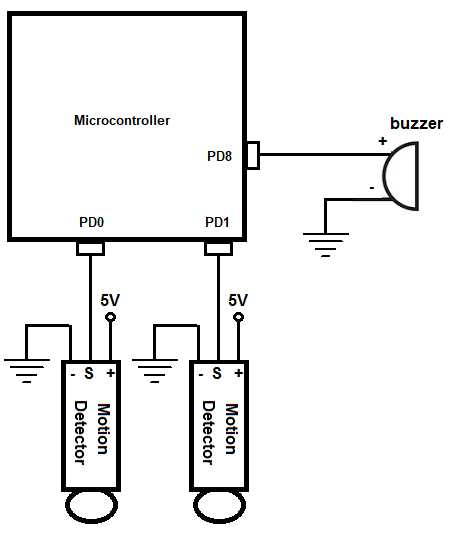
So you see that we have 2 infrared proximity sensors connected to 2 pins on PORTD on our board.
We have one buzzer connected to PD8, which will serve as our alarm for the security system.
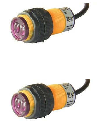
The type of motion detector sensor we will use is an infrared distance sensor.
Depending on the specific type you buy, it may be powered by either 3-5V or 12-15V or have an adjustable detection range of 0-80cm or 0-200cm.
Make sure that you get the infrared sensor powered by 3-5V because this is what the STM32F407G board supplies.
The adjustable range is up to you. 0-200cm can sense farther range, but it depends on your need. 0-80cm may be sufficient.
This is a solid sensor that allows us to detect whether an object passes in front of it.
The infrared sensor has 3 electrical pins, 2 are for power, VDD and GND. The last is the signal pin that outputs a voltage.
Read the datasheet of the infrared sensor that you purchase to find out what signal the sensor sends out when without obstacles and with obstacles.
The type that I use personally in this project sends out a 0 when there are no obstacles in front of it and sends out a 1 when there are obstacles in front of it. This is important when we are coding our software.
So when motion is detected, we have a buzzer connected to output that will buzz for 10 seconds.
So now that we have the hardware configuration, next we need the software that will sound the buzzer when motion is detected by the infrared distance sensors.
So below we show the code how to read the signal from the motion sensors and sound a buzzer for 10 second when motion is
detected by both sensors.
We now will explain the code.
We first create a delay function, which we will use later in our code in order to add a delay in order to make the buzzer sound for a specified period of time. We don't want the buzzer sounding for a millisecond. We want the buzzer to go off for a good period of time so that we are alerted that motion was detected.
Next, we define our peripheral registers.
These are the registers we must use during our program.
The first register is GPIO port D register, represented by the variable, pGPIODModeReg
If you look this up in the memory map of the datasheet for the STM32F407G discovery board, this port has a base memory address of, 0x40020C00
In order to make certain pins of GPIO port D input pins, we need to access the GPIO port input data register. This uses the GPIO port D as the base address with an added address offset of, 0x10
In order to make certain pins of GPIO port D output pins, we need to access the GPIO port output data register. This uses the GPIO PORT D as the base address with an added address offset of, 0x14
We then need to enable the peripheral clock register for the GPIOD port. The RCC, the Reset and Clock Control, for the board handles clock control. According to the memory map, the base address for the RCC is, 0x4002 3800 So RCC forms the basis for all clock control and above is the base address for RCC. What we want to do is enable the peripheral clock register, specifically for GPIOD. We enable the peripheral clock reigster via the RCC AHB1 peripheral clock register. Looking at the RCC AHB1 peripheral clock register, we see that this register has an address offset of 0x30. What this means is that we have to add the base address of RCC to this address offset of 0x30. This address gives us the address for the RCC AHB1 peripheral clock register, which is the register that allows us to work with the GPIOD port.
To enable the clock register specifically to work with GPIOD. we must set bit 3 (4th bit) of the RCC AHB1 peripheral clock register to a HIGH value.
Next, we need to set pin PD0 as an input pin to work with the motion sensor and pin PD8 as an output pin to work with the buzzer.
The *pGPIODModeReg allows us to select which pins will be inputs and which will be outputs.
Again, like all registers, the GPIO port mode register is a 32-bit register, which allows us to select which pins will be inputs and which will be outputs. Each of the 15 pins are referenced by 2 bits.
A 00 represents the pin is an input.
A 01 represents the pin is an output.
Since we want pins PD0 and PD1 to be inputs, this can done by clearing bits 1-4 of the *pGPIODModeReg variable which sets them all to 00. This is done through the line, *pGPIODModeReg &= ~(0x04);
Since we want pin PD8 to be an output, this can be done by setting 1 to pin 16 of the *pGPIODModeReg variable. This is done through the line, *pGPIODModeReg |= (1 << 16);
Next, we have our while function.
This is the code that executes over and over in an infinite loop.
The variable, *pInputDataReg, is the register that contains the data of the input pins of the PORTD register. The line, if((*pInputDataReg & (1 << 0)) && (*pInputDataReg & (1 << 1))), will be true only if bit 0 (PD0) and bit 1 (PD1) are HIGH. Only if both are HIGH does the buzzer sound.
If both sensors detect motion and thus emit HIGH signals, we turn on the buzzer by setting a 1 to the 8th bit of the variable *pOutputDataReg. This is then followed by a delay, which keeps the buzzer on for a period of time. We don't want the buzzer to sound for a fraction of a second but want it to go on for a period of time so that the user is alerted that motion has been detected, as per a typical security system.
You probably can see how this can scale up to more sensors.
All you would need to do is use more pins from the PORT D register. So if you want to add 2 more sensors to make 4 sensors, then you could use the pins, PD2 and PD3. Then you would just have to set them as inputs in the software code. The line would change to, *pGPIODModeReg &= ~(0x08);
Then after that all you would need to do is modify the if statement to accommodate the additional sensors. If you want the security system to go off when all the sensors detect motion, the if statement would change to, if((*pInputDataReg & (1 << 0)) && (*pInputDataReg & (1 << 1)) && (*pInputDataReg & (1 << 2)) && (*pInputDataReg & (1 << 3))) { }
However, you may also want to do a combination. You may not require all sensors to go HIGH to sound the system. Maybe if the first 2 bottom sensors detect motion or if 2 top sensors detect motion, then the alarm sounds. The code would be, if(((*pInputDataReg & (1 << 0)) && (*pInputDataReg & (1 << 1))) || ((*pInputDataReg & (1 << 2)) && (*pInputDataReg & (1 << 3)))) { }
So with this if statement above, if the 2 bottom sensors both detect motion or the 2 top sensors both detect motion, the system will sound.
So you could customize this according to your what you deem appropriate for the security system you want.
And this is how to create a motion detector security system circuit using an infrared distance sensor with a STM32F407G discovery board
in C.
Related Resources
How to Set Bits of a Number in C
How to Clear Bits of a Number in C