
How to Build an NPN Inductive Proximity Sensor Circuit
In this project, we will show how to connect an inductive proximity sensor to an output.
There are 2 types of inductive proximity sensors: NPN and PNP.
In this circuit, we will build an NPN inductive proximity sensor circuit. NPN is a little more complicated to hook up than a PNP transistor but still not difficult.
An inductive proximity sensor is a useful device because it can get detect metal objects. Therefore, it can be used as a metal detector device for screening when people walk through the entrance of a building or it can be be used to find metal objects such as looking for gold.
The sensor has a range of 4mm, meaning the object has to be within 4mm of the tip of the sensor to be detected. 4mm is 0.4cm or 0.157 inches away. So basically the sensor has to be right on top of the object. This can be good or bad depending on the application and use of the sensor. It's good because, since it's so close it won't pick up objects far away, confusing other metallic objects for the one in front. It's bad because the object literally has to be right on the sensor.
So, depending on the use of the sensor, it can be a very useful device in many applications. So we will
now show how to build it.
Components
- NPN Inductive Proximity Sensor
- SN7404 Inverter Chip
- NPN Transistor
- 6V Buzzer
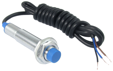
The inductive proximity sensor we will use can be obtained for just over $2 on ebay.
The sensor detects metal objects 4 meters from the tip.
It is a 3-pin sensor. The pinout of the sensor is shown below.
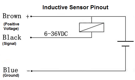
The brown pin is the positive voltage pin. Here we connect anywhere from 6V-36V.
The blue pin is the ground pin. Here we connect the pin to power ground.
The black pin is the signal pin. When the proximity sensor doesn't detect any metal objects, this pin will be HIGH, just right at the voltage that is fed the positive voltage pin, the brown pin. So, for example, if you are feeding a voltage of 6.5V into the brown pin, when no metal objects are detected, the black pin will output a voltage almost right at 6.5V, a little lower, maybe 6.3V. But for all purposes of simplicity, when no metal objects are detected, the black pin, the signal pin, emits the same voltage that is fed to the brown pin.
This inductive proximity sensor really is an output voltage device. It doesn't output much current. In order to get enough current to light up a device such as an LED or a buzzer or motor, a transistor should be used. Otherwise, the device won't be able to operate at full capacity.
In this circuit, we're going to use a SN7404 inverter gate chip to read the voltage output by the inductive proximity sensor. Using a logic chip such as an inverter is much simpler than using a chip such as a voltage comparator or even another logic gate chip such as a NAND gate, because you would have to convert that logic gate into an inverter. If you don't have an inverter but you do have a logic gate chip, then you can use that chip. You just have to know how to convert it into an inverter. A voltage comparator would be even more complex. So we're going to by with the easiest method by using an inverter gate chip.
The type of inverter gate chip we are going to use is a SN7404 chip. This is a hex inverter chip, meaning it contains 6 independent inverter gates. Each inverter gate has 1 input and 1 output. 2 pins on the chip are reserved for power, VCC and GND.
The VCC pin on the SN7404 can have a maximum of 5.5V.
In this circuit, we're going to turn on a buzzer. Since a buzzer normally requires a decent amount of
current in order to operate, we're going to connect a transistor to get current amplification. This will allow the buzzer
to sound at full force.
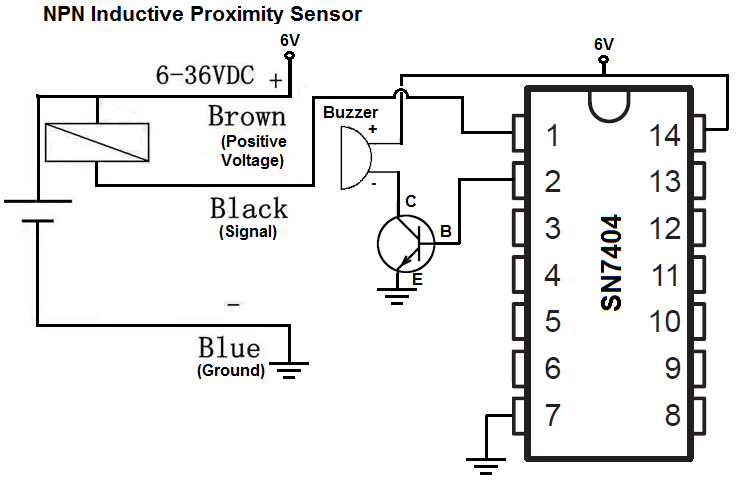
NPN Inductive Proximity Sensor Circuit
The inductive sensor circuit we will build that sounds a buzzer when metal is detected is shown below.
We will now explain the hardware connections.
First to connect power to the inductive proximity, we connect the brown pin to 6V of power and connect the blue pin to ground. This establishes power to the sensor.
To power the SN7404 Inverter gate chip, we connect 5.5V to VDD, pin 14. Then we connect pin 7 to GND. This establishes power to the Inverter gate chip.
The last remaining pin on the proximity sensor is the black pin, which is the signal pin. We connect this pin to to pin 1 of the inverter chip, which is the input to the first inverter on the SN7404 chip. It inverts the signal from LOW to HIGH or from HIGH to LOW. This is because an NPN inductive proximity sensor outputs a LOW signal when metal is detected and a HIGH signal when no metal is detected. We want to power a load when metal is detected. The NPN inductive sensor presents the happen of how we would want it. This is why we use an inverter chip to switch it around. With an inverter, the load turns on when an object is detected. And when no object is detected, the load if off. An inverter is the easiest way to function with this circuit. But there's many other ways of doing it, including using a NAND gate chip and a voltage comparator. None of these, though, will be as simple as using an inverter, which is why we chose it.
So how the circuit works is that when no object is detected, a HIGH signal is emitted on the signal line, that has a voltage just about at the voltage fed into the positive voltage pin (the brown pin). This HIGH signal is fed into the input of an inverter on the inverter chip. The inverter inverts it into a LOW signal. Thus, with this LOW signal, it's not enough voltage and current to power on the transistor and its load, the buzzer, so they're off. This, again, is when no metal is detected.
When a metal object is detected, a LOW signal is emitted on the signal line. This LOW signal is fed into the input of an inverter on the inverter chip. The inverter inverts it
into a HIGH signal. Thus, with this HIGH signal, it's enough voltage and current to power on the transistor and its load, the buzzer, so that they're on. This, again, is when a metal is detected.
So this is how an NPN proximity sensor circuit can work to power on a load when a metal is detected.
To see how this circuit works in real life, please see the video below.
Related Resources
How to Build a PNP Inductive Proximity Sensor Circuit