How to Build a Simple Thermistor Circuit
In this article, we go over how to build a simple thermistor circuit using an NTC thermistor.
A thermistor is a specialized resistor which changes resistance value depending on the amount of heat which it is exposed to. Its main characteristic is that it is thermally sensitive; in response to the heat (or temperature) it is exposed to, it alters its electrical resistance. Therefore, it can be used to measure temperature, or to sense temperature changes and act accordingly to the temperature changes, depending on its designed use for the circuit.
There are 2 main types of thermistors; negative temperature coefficient (NTC) thermistors and positive temperature coefficient (PTC) thermistors. An NTC thermistor is a thermistor whose resistance decreases when the temperature it is exposed to increases. A PTC thermistor, much less commonly used, is a thermistor whose resistance increases when the temperature it is exposed to increases.
In this article, we will use the more common NTC thermistor and build a circuit with the thermistor that can sense temperature changes.
When exposed to average room temperature, the LED in the circuit will be off. When a hot heat source such as a heater is blown on the thermistor, then the LED will turn on, alerting us to this
overheating condition.
Components Needed
- 100KΩ NTC Thermistor
- LM393 Voltage Comparator
- 50KΩ Resistor
- 330Ω Resistor
- LED
- Potentiometer
NTC thermistors can are widely available by online retailers in a number of different resistance values. You can see an assortment of thermistors at the following link- Tayda Electronics- Thermistors. However, as mentioned, in this circuit, we will use the 100KΩ thermistor. This is a thermistor that at room temperature has about 100KΩ of resistance and when exposed to very hot temperatures has a resistance in the range of 30KΩ. Thus, there is a significant drop in resistance. We will exploit this principle with a voltage comparator to build a circuit that can sense and react to these temperature changes.
The voltage comparator we will use is the LM393. This can be obtained from the same retailer at the following link- Tayda Electronics- LM393 Voltage Comparator. To find out how to use this chip extensively and to see a complete pinout and explanation of its pin, see the article, How to Build an LM393 Voltage Comparator Circuit. This comparator will is the heart of the circuit besides the heat-sensing thermistor because with it, we can detect temperatures and respond to when there are changes.
How the circuit actually operates, step by step, will be explained in full detail below.
NTC Thermistor Circuit
The NTC thermistor circuit we will build is shown below.
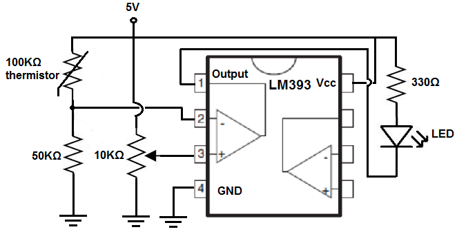
Before we begin, adjust the potentiometer so that the LED is off when there is no heat applied to the thermistor and on when heat is applied to the thermistor. The potentiometer, which can be of any value, functions as a calibrator. It sets a reference voltage level that will serve as the threshold level for what triggers the LED on and off, meaning when the voltage across the thermistor is greater than the reference voltage, the LED will be off. When the voltage across the thermistor is less than the reference voltage, the LED wil turn on. Thus, this is an important adjustment.
How this circuit works is we form a voltage divider circuit between the 100KΩ thermistor and a 50KΩ fixed resistor. At room temperature, the thermistor offers its nominal value of near 100KΩ. Voltage divides in a voltage divider circuit according to the resistance of each of the components, based on Ohm's law, V= IR. Thus, the greater the resistance of a component, the more voltage that drops across it. The lower the resistance, the less voltage that falls across it. Since at room temperature, the thermistor offers 100KΩ of resistance and the fixed resistor offers 50KΩ, most of the voltage will drop across the thermistor and very little across the fixed resistor. Thus, the voltage across the fixed resistor is very low, lower than the reference voltage set by the potentiometer. With the voltage lower at the inverting terminal than at the noninverting terminal, the output will be drawn low to ground and the LED will be off.
However, with very hot heat applied to the thermistor, its resistance drops significantly in the range of about 30KΩ. It now has a resistance below that of the fixed resistor. So most of the voltage will fall across the fixed resistor and not the thermistor. Now the voltage across the inverting terminal will be greater than at the noninverting terminal. With the voltage at the inverting terminal being greater than at the noninverting terminal, the output will be drawn to VCC and the LED will turn on.
So the LED is off when the thermistor is exposed to room temperature and on when the thermistor is exposed to very hot temperature.
And this is how a simple NTC thermistor circuit can be built.
Related Resources
Thermistor Resistance- Explained
How to Test a Thermistor