
How Open Drain Output Configuration Works in an STM32 Board

In this article, we explain open drain output configuration works in an STM32 board.
There are 2 types of configuration modes we can place an output in for a GPIO pin.
These output configuration modes are either push-pull or open drain.
This is shown below in the GPIO port output type register (GPIOx_OTYPER),
which allows for the selection
of either Output push-pull or Output open-drain.
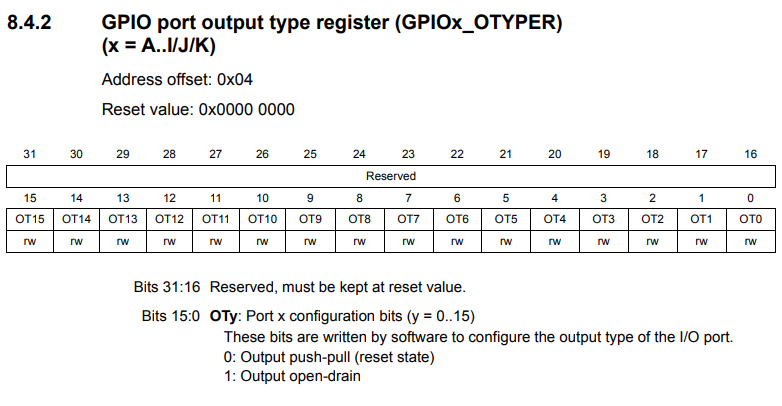
By default, all output GPIO pins are in push-pull state, unless open-drain state is explicitly selected with this register.
Push-pull state is the state that most imagine an output to behave in. This state has an output value of either ON or OFF, as a digital device behaves. With push-pull state, the output is either ON (a HIGH logic state) or OFF (a LOW logic state).
Open-drain output configuration mode is either OFF (or GND) or in floating state.
Let's now look at the structure of a GPIO pin port bit shown below.
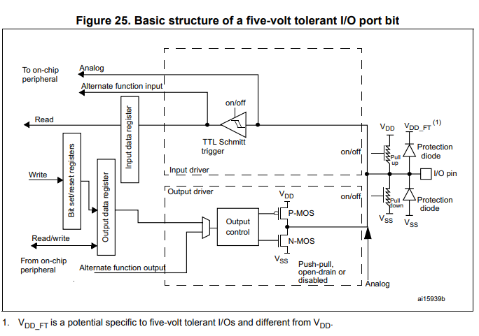
So how writing to an output works is that input a HIGH or LOW output state into the output data register and this goes into the Output Control.
You can see 2 MOSFET transistors that appear after the Output control box.
In Open-drain configuration, the P-MOS transistor is completely disabled, so it is as if the P-MOS transistor doesn't exist or is completely taken out.
This is shown in the diagram below.
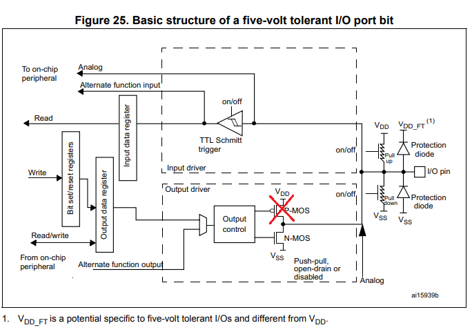
So in the open-drain configuration, the P-MOS transistor is completely disactivated and it is as if it is not there.
So the only thing that remains in the open-drain output configuration mode is the N-MOS transistor.
A MOSFET has 3 terminals: the gate, the drain, and the source.
The gate is the terminal directly connected to the Output control box.
The source is the terminal connected to GND or VSS.
The last terminal, the drain, is the terminal connecdted to the P-MOS transistor.
When a 1 or HIGH logic state is input into the gate of the N-MOS transistor, the transistor turns on and current flows down to the VSS or GND. This connects the output connected at the I/O pin to GND; therefore, the device will be OFF.
When a 0 or LOW logic state is input into the gate of the N-MOS transistor, the transistor doesn't turn ON and is just in a high-impedance state. This makes the drain terminal in a floating state. In a floating state, the logic level of the drain may be LOW or HIGH and may switch back and forth randomly from LOW and HIGH state, as it is susceptible to state changes due to noise.
So this means that in order to give the drain terminal a defined state, we must use a pull-up or pull-down resistor.
A pull-up resistor (to VDD) gives the drain a HIGH state.
A pull-down resistor (to VSS0 gives the drain a LOW state.
You may use an internal or external pull-up or pull-down resistor.
Which you choose to use may depend on what your circuit is powering.
You cannot choose the value of the internal pull-up resistor of the STM32 board, as the internal pull-up resistors are a fixed value. This value for most GPIO pins is 40KΩ. Therefore, if you are trying to power a device such as an LED, this wouldn't work, as the current would be so small as to not be sufficient enough to power it on. Therefore, in this situation, you would have to use an external resistor that is much smaller that would be able to power on the LED.
So when would you use an open-drain output configuration?
There are cases where you would want to use open-drain configuration over push-pull.
One of the most common reasons is when using certain serial communication methods such as I2C.
When using GPIO pins to function for I2C communication with another device, the protocol specifies that open-drain configuration is required, where there is a high-impedance or floating state.
The communication interface will then pull it HIGH or pull it LOW based on the data.
So one of the most common uses of open-drain is not when you are connecting output devices
such as LEDs or motors to the I/O pins, but for various communication protocols that require it.
And this is how open-drain output configuration works in an STM32 microcontroller
board.
Related Resources