
How to Build an Optocoupler Circuit
In this project, we will show how to connect an optocoupler chip to a circuit.
An optocoupler or optoisolator chip is a chip that allows for electrical isolation between the input of the circuit and the output of the circuit.
By electrical isolation, we mean that the power going into the input has no effect whatsoever on the power on the output. The power sources are isolated, so they are completely independent. So if the power to the input is changed, this does not affect the power on the output, and vice versa.
Electrical isolation can be very important, especially in circuits where the input power to the circuit is very high and there are other parts in the circuit that only require a very small amount of power. So if there is an incident such as a surge of power into the input of the circuit, it doesn't affect the area that only requires a small amount of power, since it's isolated from the input. This would be the main application and use for optoisolators. Optocouplers can also be used if the input power may bring in a lot of noise, which for many applications can be very undesirable. To separate this noise from being induced into the output, electrical isolation is necessary and solves the problem.
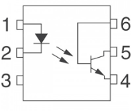
How optocouplers work is they provide isolation through an IR LED and phototransistor. With this setup, there's no direct conductive path from the input to the output of the circuit. Instead, an IR LED beams its infrared light onto the phototransistor. Being that there's no direct conductive pathway, the input and output aren't linked, so there's electrical isolation.
The chip we will use is the popular 4N35 optocoupler chip.
We will show how to wire this chip up to any circuit so that you can obtain electrical isolation as needed.
This is a just basic circuit showing how to connect up a photocoupler IC. We aren't going to use any very high voltages. It's going to be very simple. But after, you'll know how to
wire up any type of photocoupler IC.
Components
- 4N35 Photocoupler Chip
- 2 470Ω resistors
- LED
- Toggle Switch
The 4N35 optocoupler (optoislator) chip can be obtained from a number of online retailers for a very inexpensive price.
The 4N35 is a 6-pin IC. Its pinout is shown below.
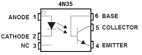
And how it works is we give enough power to the anode and cathode pins, so that the LED is sufficient power to turn on. Once on, it beams infrared light onto the phototransistor. With infrared, the phototransistor can conduct across from collector to emitter and power on any load connected to the output, which in this case is a LED.
And now there is isolation between the input and output of the circuit.
A rundown of all the pin connections is shown in the table below.
4N35 Optocoupler Table
| Pin | Pin Description | Connections |
| 1 | Anode | The input voltage to turn on the IR LED is connected here. |
| 2 | Cathode | This connects to ground. |
| 3 | NC | This remains unconnected. |
| 4 | Emitter | The emitter gets connected to ground. |
| 5 | Collector | The output and power connects to the collector terminal. |
| 6 | Base | This remains unconnected. |
So these are all the pin connections.
The first 2 pins are the anode and the cathode. These power on the IR LED. Without these being powered, the output side cannot turn on, because the phototransistor needs infrared (IR) light in order to conduct. Therefore, without the IR LED being on, the phototransistor will be in nonconduction move and no current can flow through the phototransistor, meaning anything connected to output will not be powered. So a few volts are needed to power on the IR LED.
The third pin is left unconnected.
We connect the emitter terminal to ground.
We connect the output and the voltage necessary to power the output to the collector terminal.
And we leave the base terminal of the phototransistor unconnected. A lot of optocoupler chips do not even have a terminal for the base because it's unnecessary to connect it.
Optocoupler Circuit
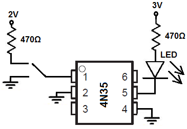
The optocoupler circuit we will build with a 4N35 chip is shown below.
This above circuit built on a breadboard is shown below.
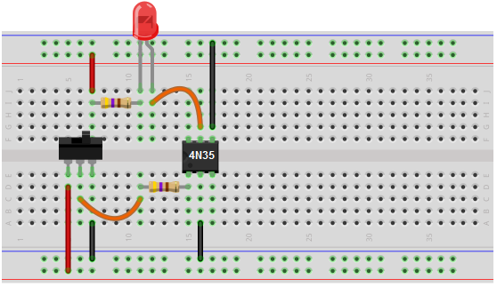
A toggle switch was placed on the input side of the optocoupler circuit in order to switch on and off the circuit. Being that the optocoupler cannot work unless the IR LED is on, we can switch on and off the circuit by turning this IR LED on or off. And this controls the entire circuit.
When switched on, the phototransistor receives IR light and conducts.
When off, the phototransistor cannot conduct.
On the output side, being there is electrical isolation, we need to place a power source so that the load, in this case, an LED can turn on. So we connect a 3V power supply source to the collector and this powers on the LED.
And this is how an optocoupler circuit works.
To see the real-life circuit of it below, see the video below.
Related Resources
How to Build a Dark-activated Switch