
How to Build an Overvoltage Protection Circuit
An overvoltage protection circuit is a circuit which protects electronics from excess voltage, which could potentially damage or destroy electronic components.
In this project, we will build a simple, yet effective, overvoltage protection circuit using a fuse and a zener diode, as the protecting elements, that will work for electronics that operate with DC voltage.
Again, this circuit is only effective with circuits which operate off of DC power, which most electronic gadgets do.
The parts we will use to build this circuit are:
Components Needed
- Zener Diode
- Fuse
- Input Voltage Source
- Jumper wires
The zener diode that you will choose depends on how much voltage you want to limit the circuit to. Zener diodes are rated with all differing amounts of breakdown voltage ratings. The breakdown voltage is the amount of reverse voltage which a zener diode can receive before it breaks down and begins conducting reverse current across its junctions. A zener diode will not conduct current across its terminals unless this threshold breakdown voltage is reached. Before the threshold voltage is reached, zener diodes will simply "hold" the voltage across its terminals that is exposed to. For example, if a zener diode is rated for a breakdown voltage of 12V and it is exposed to a voltage of 3V, it will simply hold the 3V across its terminals and not conduct any current across its terminals. If the voltage reaches above 12V, then the zener diode will break down and conduct current across its terminals. Therefore, use the zener diode with a voltage rating that you want to limit your circuit to.
If you want to limit your circuit to 5V, then use a zener diode with a breakdown voltage rating of 5V. After this 5V threshold is reached, the zener diode will conduct current across its terminals and shunt excess power to ground. If you want to limit your circuit to 12V, then choose a zener diode with a breakdown voltage rating of 12V. After this threshold is reached, the diode will break down and shunt all excess power to ground. While "broken open", the zener diode will no longer hold voltage across its terminals, so the load in parallel with the zener will not receive this excess voltage.
The fuse in this circuit really serves to be an additional protection to the zener. If the voltage is exceeded and, thus, the zener breaks down and conducts current, the fuse will break open if the current exceeds a certain amount, which is determined by the current rating of the fuse. The fuse that you will need is the amount of current you want to limit your circuit to. There are all types of fuses available to limit differing amounts of currents. Some fuses limit current to 1 amp. Others 2 amperes. Others 3 amperes. Whatever current you want to limit the circuit to is the fuse that you will choose. For example, if you want no more than 500mA of current to flow through your circuit, you will choose a 0.5amp fuse. This fuse will blow when this threshold is reached. Therefore, it serves to protect the circuit against excess current, while the diode serves to protect the circuit for excess voltage.
The input voltage source can be from any power source such as batteries or a DC power supply. And you'll need a few jumper wires to
connect all electronics components together.
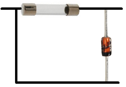
Overvoltage Protection Circuit
The circuit we will build is shown below:

Again, you choose the voltage rating of the zener based on the voltage you want the load to be limited to. And you choose the current rating for the fuse based on what current you don't want the circuit to be exposed to.
Since voltage in parallel is equal across all components in a circuit, the voltage that falls across the zener diode will fall across the load in parallel with the zener diode. So by choosing the voltage rating of the zener carefully, we decide the voltage that the load will receive. If we choose a zener with a breakdown voltage rating of 5V, then the load will received 5V when the zener receives 5V. After this amount, the zener will break down and conduct current to ground. Since its resistance has broken down and it is now conducting, its voltage drops dramatically, so the load in parallel does not receive this excess voltage.
And this is how a simple overvoltage protection circuit can be built with a zener diode and a fuse.
Related Resources
Types of Diodes
What is a Varactor?
What is a Protection Diode?
What is a Photodiode?
What is a Shockley Diode?
What is a Fast Recovery Diode?