
PIC16F690 Microcontroller Circuit- How to Drive an LED Display
In this article, we will show how to drive a 7 segment LED Display using a PIC16F690 microcontroller.
This PIC16F690 microcontroller chip is actually a part of the PIC2 Starter Kit, so we will actually be using this starter kit to drive the LED Display.
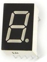
A 7 Segment LED Display is an electronic device that contains 8 individual LEDs. Each of the LEDs can either be on or off. Depending on which LEDs are lit determines the character which is displayed. The LED display can show any number from 0 to 9. It can also show many alphabetical characters.
In this project, we will use the PIC16F690 microchip contained in the PIC2 Starter Kit to control the 7 segment LED display so that we can light up whichever segments we want to display whatever characters we want in sequence.
A 7 segment LED display is a valuable electronic device because used in conjunction with other LED displays, it can function as a numerical display, such as time for a clock, a display for a game scoreboard, or any such other numerical display. So it is a very valuable electronic device to know how to operate.
Using a microcontroller to drive an LED display is much more easy and efficient than not. If we did not have a microcontroller to drive an LED, in order to display different numerical values, we would need someone to manually change which turn on or off different LEDs in the LED display. This would be much less efficient than using a microcontroller. When a microcontroller, in this case a PIC16F690 microcontroller, is connected to an LED display, all we need to do to change the software to display different characters. Changing the hardware, which LEDs are lit, is much more complex and time-consuming and, thus, is simply not efficient.
We will now show how to connect and program the PIC16F690 microcontroller to drive an LED display. Specifically, for this circuit, we will drive one LED display, for simplicity, to count from 0 to 0 and then reset back to 0.
Again, a 7 segment LED sipaly is made up of 8 individual LEDs. Thus, the microcontroller needs enough I/O pins to connect to each of the 8 terminals of the 7 segment LED display. It's the job of the software to light them in the proper order to create the numbers 0 to 9.
For this project, we will use a common anode LED display, which is a display all the anode leads are common and
the cathode leads are not. To understand the difference between common anode and common cathode displays, see
What is a 7 Segment LED Display.
Circuit Schematic
The schematic of the PIC16F590 microcontroller chip connected to the LED display is shown below:
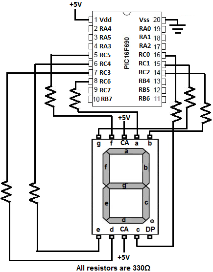
The PIC16F690 can drive an LED directly from an I/O pin because it can output up to 25ma of current. The whole port can supply 200ma in total maximum. We connect 330Ω resistors to the outputs to limit current so that the LEDs don't receive too much current and burn out. They are safety current-limiting resistors.
The only connections we need is 5 volts of power to the Vdd pin and to have the Vss pin connected to ground. However, if you plug in the PICkit 2 programmer, you can get power from it and, thus, would not have to make power connections. This reduces more connections.
The PIC16F690 has an internal oscillator that we will run at the default speed of 4MHz. The MCLR master clear reset pin will be set to internal mode so we don't need any external reset circuitry. Those are both setup in the configuration register of the PIC16F690. We control that configuration in the software.
Being that the LED display is common anode, all the anodes are tied together (are common). The cathodes are separate
and tie down to ground. For an LED to have a complete circuit and turn on, the LED needs to connect to ground. This will happen
if its cathode terminal is connected to ground. Thus, if an LED segment is connected to ground it is on. This is why an LED turns
on if it is low. If the LED is connected only to the anode's positive voltage, it is HIGH and off. This will be important when
coding, because a 0 will represent an ON LED and a 1 will represent an OFF LED.
Code to Drive LED Display
The code need to drive an LED display is written for the HI-TECH PICC PRO compiler. This can be done in lite mode.
This will sequence 0 to 9 at a 1/2 second rate. It is a common anode display driven by PortC.
The first line of code includes the header for the HI-TECH compiler. This pulls in all files required by the compiler and needs to be part of every HI-TECH project.
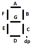
The next block of code creates the digits we will display. How this works will be explained now in depth. As discussed, the LED display has 8 connections. The 7 connections
A-G allow us to show numerals on the display and the dp LED allows us to display a decimal. The common anode display starts at LED at the top, which represents A. Then it goes clockwise all around
to in order till it reaches F. The LED at the center is G. Since, in the schematic, we connect RC0 to LED C, PortC.0 is C. Since we connect RC1 to LED G, PORTC.1 is G. Since we connect RC2 to LED
B, PORTC.2 is B. Since we connect RC3 to D, PORTC.3 is D. Since we connect RC4 to E, PORTC.4 is E. Since we connect RC5 to F, PORTC.5 is F. Since we connect RC6 to A, PORTC.6 is A. Since we connect
RC7 to dp, PORTC.7 is dp. So the order is (dp)AFEDBGC.
What all of this means is this. Say if we want to show the number 2. This means that all of the LEDs will be on, except for LEDs F and C and dp. How each LED is represented is in binary.
Since the LED display is active low, a 0 means the LED is on and a 1 means the LED is off. So to display a 2, the binary code will be 0b10100001. The leftmost bit is C. The rightmost bit is dp.
The full order is (dp)AFEDBGC.
So now you see where these values come from.
The next block of code is a configuration. It sets the internal clock, keeps the watchdog off, MCLR off, and makes the code unprotected.
The main function creates a variable called state_led. This variable is initialized to be 0. It starts at 0. It will be made to increment by 1 after each run of the while loop. This
makes it go through each of the switch statements that appears next in code. After it reaches to 9, it goes back to 0.
In this block as well, ports and comparators are initialized. It clears PORTC to start with all the LEDs off and declares all the ports of PORTC as output pins, so that we can display values
to them (turn off or on the LEDs).
In this main loop is an infinite while loop. It is created so that it always runs. In embedded applications, we always want the microprocessor to run code. If you're interested in learning
more about the importance of the while(1) loop, see Embedded C programming- while(1). In this while loop, are
switch statements. These execute in order. Once it reaches to 9, it starts over at 0.
In this program, we create a 0.5 second pause between each incremental showing. You can keep it the same or adjust this depending on the time you want to pass between each number
showing.
These 2 other C programs have to go and be compiled when running the above main.C code.
These 2 files are pause.C and msecbase.c.
PAUSE.C This code creates and defines the pause() function. We use this pause() function in the main program in order to check the switch count every half a second (500 milliseconds).
Thus, every 500 milliseconds, the LED will switch numbers and increment one to its number.
MSECBASE.C This msecbase.C code creates a 1 msec pause routine. This allows us to have a 1 millisecond pause in our program. To do this, we must set the internal timer, timer 0, of the
PIC16F690 chip correctly to produce a 1ms delay. The internal oscillator is set to 4MHz and the internal instruction clock is set to 1/4 of the oscillator. This makes the internal instruction
clock 1MHz, which is 1 microsecond per clock pulse. Using the 1:4 prescaler on the clock input to Timer0 slows the Timer0 count increment to 1 count/4μs. Therefore 250 counts of the Timer0 would make a
1 millisecond delay (250 * 4μs). But there are other instructions in the delay loop so using the MPLAB stopwatch, we find that we need Timer0 to overflow at 243 clock ticks. Preset Timer0 to 13 (0D hex) to make Timer0
overflow at 243 clock ticks (256-13 = 243). This results in a 1.001 millisecond delay, which is close enough to 1.
Connections
PORTC.0- C
PORTC.1- G
PORTC.2- B
PORTC.3- D
PORTC.4- E
PORTC.5- F
PORTC.6- A
PORTC.7- dp
/*
const zero= 0b10000010;
const one= 0b11111010;
const two= 0b10100001;
const three= 0b10110000;
const four= 0b11011000;
const five= 0b10010100;
const six= 0b10000100;
const seven= 0b10111010;
const eight= 0b10000000;
const nine= 0b10010000;
void pause (unsigned short usvalue);
main()
{
unsigned char state_led= 0;
CM2CON0= 0;
PORTC= 0x00;
TRISC= 0x00;
while (1)
{
state_led++;
switch (state_led)
{
case 1:
PORTC=one;
break;
case 2:
PORTC= two;
break;
case 3:
PORTC= three;
break;
case 4:
PORTC= four;
break;
case 5:
PORTC= five;
break;
case 6:
PORTC= six;
break;
case 7:
PORTC= seven;
break;
case 8:
PORTC= eight;
break;
case 9:
PORTC= nine;
break;
default:
state_led= 0;
PORTC= zero;
break;
}
pause(500);
}
}