
How to Build a Peristaltic Pump Circuit Controlled By an Arduino
A peristaltic pump is a pump, operated by a motor, that is able to uptake a liquid through one tube and drip it out through another tube.
The point is that it can uptake a liquid and redistribute to another place in need of that liquid.
You can place one tube in a bucket of water and the other tube at the base of a plant, and it can give the plant water at any time interval needed, like, for example, every 8 hours.
A peristaltic pump probably gets its name from the word peristalsis, which means wave-like movement. In biology, peristalsis is the wave-like muscle contractions that moves food to different areas of the body. First, peristalsis occurs when you swallow food. Food moves down the esophagus to the stomach through peristalsis and then again through the small intestine. Without getting too deep into biology, just know that peristalsis involves movement. A peristaltic pump moves liquids through it from one tube to the other tube.
A peristaltic pump can form a wide variety of uses but its function is transport a liquid from one area to another. It can transport any liquid. It can be used for watering plants if one tube is in water and the other tube is at the base of the plant.
Before, in a previous circuit, we built a most basic peristaltic pump circuit where we simply connect power to the motor for it to operate. Now in this circuit, we connect the peristaltic pump to an arduino microcontroller so that we can run it at regularly scheduled time intervals. This allows for greater and complex control over the operation of the pump. We may not want the pump always operating continuously; with a microcontroller we can let it run at any time we want. For example, you may want it watering a plant every 12 hours or so. With a microcontroller such as the arduino, we can do this watering autonomously. And we can choose how long we want the pump on for.
Components
- Peristaltic pump
- PN2222 NPN Transistor
- 1N4001 Diode
- Arduino microcontroller
You can obtain a peristaltic pump on ebay for about $10-$12 or so.
It comes either as a 6V pump or a 12V pump.
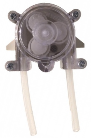
A peristaltic pump is basically a DC motor. It operates just like a motor. It is a motor.
It has 2 terminals for connection.
Just like a motor, it will work regardless of the how the voltage source is connected to it in regards to polarity. However, if you switch the polarity, water will be pumped the opposite way.
On many peristaltic pumps, one tube is longer than the other. If you want the longer tube to be the
tube uptaking the liquid, then the positive terminal voltage has to be connected to this end. Whatever terminal
of the pump has the positive terminal voltage will be the tube uptaking the liquid. The other tube, that has the
ground terminal of the power source connected to it, will be dispersing the liquid in drops. So keep this in mind
when connecting power to the peristaltic pump.
Peristaltic Pump Controlled By an Arduino
The peristaltic pump circuit we will build to be controlled by an
arduino is shown below.
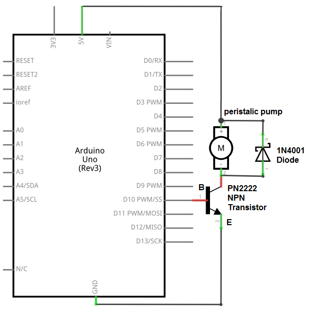
So in this circuit, the connections are fairly basic.
Because the arduino micrcontroller does not output enough current to drive the peristaltic pump, it needs a transistor, which gives it current amplification, for it to have enough current to drive the peristaltic pump. Now the peristaltic pump can operate on 5V on power. However, it wouldn't be super fast in operation. If you don't mind this, you can use the 5V that the arduino provides to operate the pump. However, if you want operating fast and at full power, then you'll need to connect an external voltage source to the transistor. 12V makes it operate at pretty much full capacity and fast. 5V will just get it dripping.
We connect one of the digital pins to the base of the transistor. In this circuit, we connect digital pin 10 to the base of the transistor. Because a transistor needs current at its base in order to operate, the transistor cannot turn on unless it receives sufficient at the base. If you keep digital pin 10 LOW, meaning it gets no power, the transistor cannot turn on. Thus, the peristaltic will be off as long as digital write pin 10 LOW. However, if we write it HIGH, then the base receives sufficient and turns the transistor on. Now the peristaltic pump turns on. So we use the arduino in this case to turn the transistor, and, thus, peristaltic pump on and off.
The collector of the transistor connects to either 5V from the arduino or the external voltage source and the peristaltic pump. So we connect power source and the load to the collector of the transistor.
The emitter of the transistor simply gets connected to ground.
And we connect what's called a flyback diode in parallel with the motor. This protects the arduino micrcontroller from back emf produced by the motor. A motor is a device that can produce surges of harmful power that can possibly damage a microcontroller or any electronic device. To protect from this, many times a diode is placed parallel reverse biased to protect from these harmful effects.
This completes all the hardware connections. Next all we need is the code.
Code
The code to turn on a peristaltic pump for 5 seconds every 30 seconds is shown below.
const int motor= 10;
void setup()
{
pinMode(motor, OUTPUT);
}
void loop()
{
digitalWrite(motor,HIGH);
delay(5000);
digitalWrite(motor,LOW);
delay(30000);
}
Since the motor is connected to digital pin 10, we set the motor variable to the value of 10.
Next, we have our setup() function, which makes the motor an output device, since we're writing to the motor.
After this, we have our loop() function. In this code, we set it up so that the peristaltic pump is on for 5 seconds every seconds. So at first, we turn it on, leave it on for 5 seconds, and then turn it off for 30 seconds. This repeats over and over again. You can modify these values to suit your needs.
And this is how a peristaltic pump can be controlled with an arduino microcontroller.
To see how this circuit works in real life, see the following video below.