
How to Build a Proximity Detector Circuit
In this project, we will build a proximity detector circuit.
A proximity detector is gagdet that detects when an object is nearby.
There are 2 ways to build a proximity detector using IR LEDs and IR phototransistors.
One is mount the IR LED and the phototransistor so that they face each other. Then the infrared light is detected by the phototransistor. If an object comes between the IR LED and the phototransistor, the light is blocked, and the phototransistor turns off.
The other way is to build a proximity detector is to mount the IR LED and the IR photodiode next to each other facing the same direction. When an object comes near the IR LED, some infrared light will bounce off the object and be detected by the phototransistor.
In this project, we will build the former. We will place an IR LED and phototransistor so that they face each other. Thus, the phototransistor will normally be in
conductive state. Only when an object comes in between the IR LED and the IR phototransistor will the phototransistor no longer conduct, because it doesn't have the infrared light beaming on it.
Components Needed
- 940nm IR LED
- 940nm Phototransistor
- 3 470Ω Resistor
- 4081 AND gate chip
- LED
The IR LED and the IR phototransistor has to be of the same wavelength. In this circuit, we will use a 940nm IR LED and phototransistor. But if you have another matching set, that can be used as well.
We will use the IR LED and IR phototransistor with a 4081 AND gate chip. This is a chip that can read input voltage levels and can determine whether the voltage is HIGH (above 1/2 of the supply voltage to the chip) or LOW (below 1/2 of the supply voltage). Thus, we use this NAND gate chip as a way of knowing voltage levels. Why this is important is because this voltage input will determine whether there is an object in between the IR LED and the IR phototransistor or not.
Normally, when the IR LED and the phototransistor are unimpeded, so that the phototransistor receives infrared light from the IR LED, current flows through the phototransistor. If you place a jumper wire after the resistor connected to the collector of the phototransistor, this can measure different voltage values when there is current flowing through the phototransistor (no object impeding the IR LED and IR phototransistor) and when there is no current flowing (object is impeding the IR LED from the IR phototransistor). It is through this jumper wire after the resistor on the collector terminal that allows us to know whether the transistor is conducting or not.
When the phototransistor is not conducting, the jumper wire will have a voltage that is close to the supply voltage on the collector terminal. This is when there is no current flowing through the phototransistor. This occurs when an object is impeding the IR LED and the IR phototransistor. This is how we know an object is there. Feeding this into the AND gate chip, we can know whether this voltage is HIGH (object detected) or LOW (no object detected).
When the phototransistor is conducting, the jumper wire's voltage will drop significantly to less than 1/2 of the supply voltage to the AND gate chip. This is when there is current flowing through the phototransistor. This occurs when no object is detected. Thus, the voltage will be LOW. If the phototransistor is not conducting, the jumper wiper's voltage will be greater than 1/2 the supply voltage to the AND gate. This occurs when an object is detected. Thus, the voltage will be HIGH.
So the AND gate chip can know whether there is an object detected or not by this voltage from the jumper wire after the resistor. An AND gate will produce a HIGH output when there is an object detected between the IR LED and the phototransistor. And it will produce a LOW output when there is no object detected. Thus, the output LED will turn on when an objected is detected and will be OFF when no object is detected.
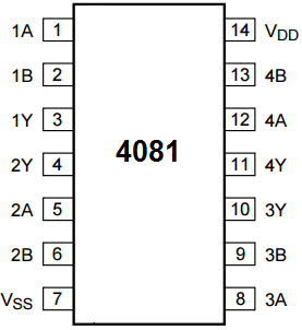
The 4081 is an AND gate chip.
The pinout of the 4081 is shown below, so that you can see how to connect it in the circuit.
An AND gate will only turn its output HIGH when both inputs are HIGH.
Since we tie both inputs together, it will produce a HIGH on the output when a HIGH input voltage is fed into
it.
Proximity Detector Circuit
The schematic diagram of the proximity detector circuit we will build is shown below.

The above circuit shown on a breadboard is shown below.
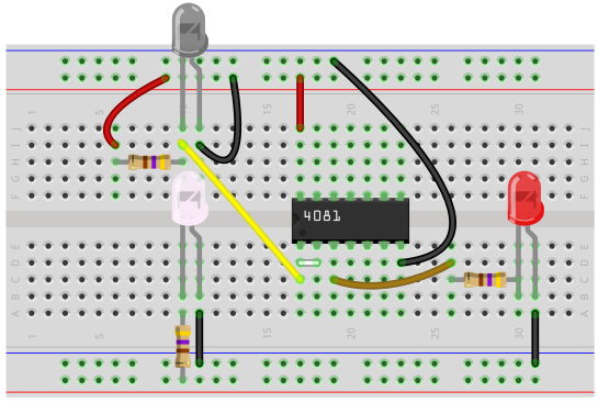
So the IR LED and the phototransistor should be placed so that the IR LED can beam the infrared on the phototransistor.
There should be a space in between them, though, so that if an object passes through in between them, it can be detected by the circuit.
And how it works is when the object passes between the IR LED and the phototransistor, it blocks the phototransistor from receiving the infrared. When this happens, the voltage at the collector terminal is HIGH. Being that we tied the 2 inputs of the AND gate together, this makes both inputs to the AND gate HIGH. When both inputs are HIGH to a 2-input AND gate, the output is HIGH. So, in this case when an object is impeding infrared light from being transmitted to the IR phototransistor, the output LED is ON.
If no object is impeding the infrared light from the phototransistor, then the phototransistor conducts current. When it conducts current, the voltage at the collector terminals drops to a LOW state. When it drops to a LOW state, the output of the AND gate is LOW. Therefore, the output LED is off.
And this one way of building a proximity detector circuit.
Related Resources
How to Build an IR LED Circuit