
How to Create a Push Button Circuit with a STM32F407G Discovery Board in C

In this article, we go over how to create a push button circuit with an STM32F407G discovery board in C.
This enables us to add a push button to the board so that we can accept user input.
We will use the simplest type of push button for this demonstration, a single pole single throw push button. We combine this with a pull-up resistor to create standard push button functionality.
So working with a push button requires that we connect the pushbutton to a general purpose I/O pin that is configured as input. We must then be able to read this input and, thus, can then take actions based on this such as turn on an LED when the push button is pressed.
We will configure pin 0 of PORTA as the input. This is the pin where we will attach the push button to.
Normally, without being pressed, the push button will be a LOW voltage status, meaning it inputs a 0 to the circuit.
When pressed, however, the push button will be a HIGH voltage status, meaning it inputs a 1 to the circuit.
The circuit we will build is shown below.
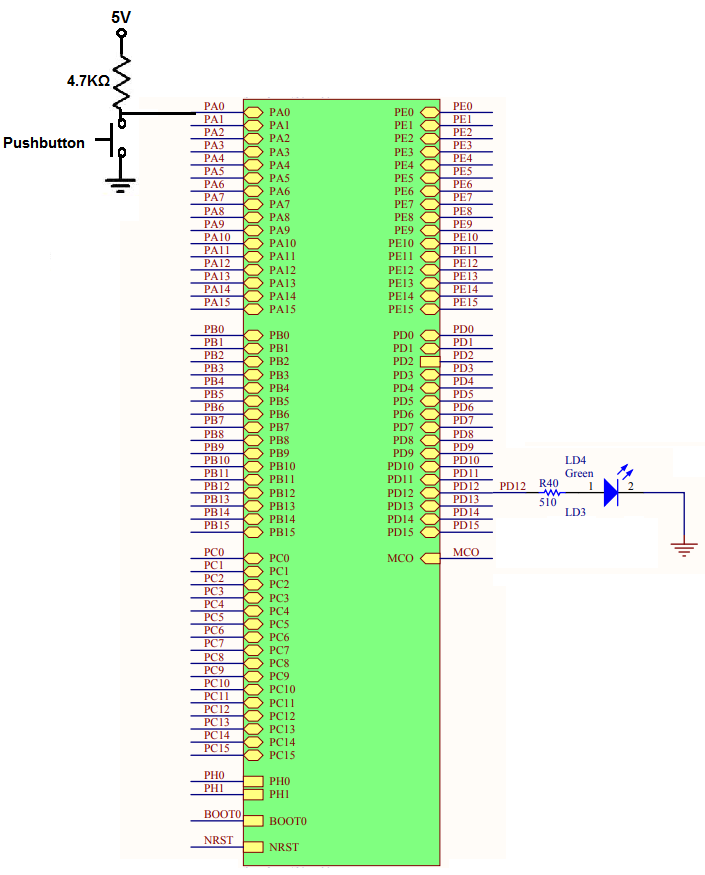
So the only thing you have to add to the STM32F407G board is the resistor attached to VDD and then the pushbutton attached to ground. The push button should be a normally open push button, meaning it does not make electrical connection to VDD unless it is pressed down.
The LED we turn on is already connected on board, so no LED or resistor needs to be connected to the circuit. It's already built on board.
So now that we have the hardware configuration, next we need the software that will detect the push button and then can perform an action such as turn on an LED.
So below we show the code how to detect a user button press which will then
turn on LED on PORTD pin 12, which is a green LED.
We now will explain the code.
Within our main function, we declare 3 32-bit variables.
These variables are crucial and form the foundation for our code.
So the first variable is for the clock control register, so that we can enable the peripheral clock register.
The RCC, the Reset and Clock Control, for the board handles clock control.
According to the memory map, the base address for the RCC is, 0x4002 3800
So RCC forms the basis for all clock control and above is the base address for RCC.
What we want to do is enable the peripheral clock register, specifically for GPIO.
The following image below helps us to navigate this.
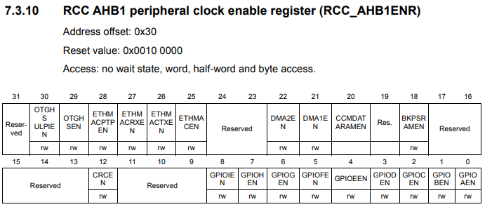
Looking at the RCC AHB1 peripheral clock register, we see that this register has an address offset of 0x30. What this means is that we have to add the base address of RCC to this address offset of 0x30. This gives us a result of, 0x4002 3800 + 0x30, is 0x4002 3830.
This address gives us the address for the RCC AHB1 peripheral clock register, which is the register that allows us to work with the GPIOA and GPIOD ports.
The only other thing we must do is set the clock register specifically to work with ports GPIOA and GPIOD. To do this, we must set bit 0 (1st bit) of the RCC AHB1 peripheral clock to a HIGH value to work with GPIOA. We set bit 3 (4th bit) of the RCC AHB1 peripheral clock register to a HIGH value to work with GPIOD.
We do this in the line, *pClkCtrlReg |= (1 << 3);
This sets bit 3 to HIGH, which enables the peripheral clock register for the GPIOD port.
The line, *pClkCtrlReg |= (1 << 0);, sets bit 0 to a HIGH, which enables the peripheral clock register for the GPIOA port.
Next, we need to configure the GPIO port mode register.
The diagram below helps us to navigate this.
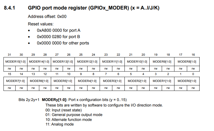
This is where we can configure pins of the port as input or output.
The base address for the GPIOD port is, 0x4002 0C00
The GPIO port mode register has an address offset of 0x00.
In order to turn on pin 12, we see that this register is a 32-bit register, and bits 24 and 25 correspond to bit 12 of the GPIO port.
As can be see in the MODE configuration bits, 00 makes the pin an input, 01 makes the pin an output, 10 gives an alternate function mode, and 11 makes the pin analog.
In this case, since we want to turn on an LED, we want to make pin 12 an output, so we want to set the bits 24 and 25 to 01.
This is done in the line, *pPortDModeReg |= (1 << 24);
Now to configure the PORTA pin 0 as input, we first need to look up that the base address of PORTA is, 0x40020000
This is shown in our code in the line, uint32_t *pPortAModeReg= (uint32_t*)0x40020000;
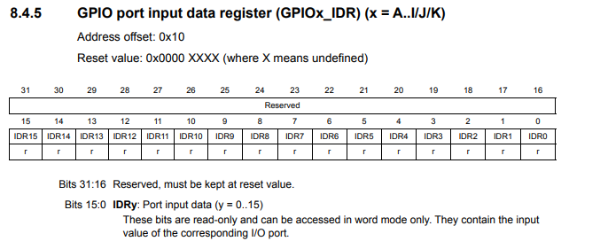
If looking up the GPIO port input data register, which enables a PORT to function as input, we see that it has an address offset of 0x10. We add this offset to the base address of the GPIOA register to get an address of 0x40020010;
This is shown in our code in the line, uint32_t *pPortAInReg= (uint32_t*)0x40020010;
This is shown in the diagram below.
Next, we must configure pin 0 as input, which we do through the line, *pPortAModeReg &= ~(3 << 0);
Pin 0 comprises bits 0 and 1 of the GPIO Port Mode Register. To make a pin an input, we set the pin to a value of 00.
3 really is 11 in binary. The negation, ~, makes it a 00 that we write to bits 0 and 1.
We then create a while loop that loops forever. This is important because we always constantly want to be assessing the value of the input being read at GPIOA pin 0, which is the pin connected to the push button.
We create an 8-bit variable, pinStatus, which allows us to read the input logic state at GPIOA pin 0, the push button.
Realize that this is an 8-bit variable and we only want to read 1 bit, bit 0. Therefore we AND the result with 0x1, which is a binary 1. This is the same as 00000001. This zeroes out all the bits other than bit 0.
We then have an if statement. If input read is a logic HIGH, then we turn the LED on using the line, *pPortDOutReg |= (1 << 12);
If the input read is a logic LOW, then we turn off the LED using the line, *pPortDOutReg &= ~(1 << 12);
And this is how to create a push button circuit that can read user input with a STM32F407G discovery board
in C.
Related Resources
How to Set Bits of a Number in C
How to Clear Bits of a Number in C