
How Push-Pull Output Configuration Works in an STM32 Board

In this article, we explain how push-pull output configuration works in an STM32 board.
There are 2 types of configuration modes we can place an output in for a GPIO pin.
These output configuration modes are either push-pull or open drain.
This is shown below in the GPIO port output type register (GPIOx_OTYPER),
which allows for the selection
of either Output push-pull or Output open-drain.
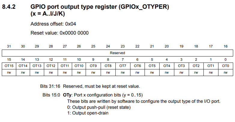
By default, all output GPIO pins are in push-pull state, unless open-drain state is explicitly selected with this register.
Push-pull state is the state that most imagine an output to behave in. This state has an output value of either ON or OFF, as a digital device behaves. With push-pull state, the output is either ON (a HIGH logic state) or OFF (a LOW logic state).
Open-drain output configuration mode is either OFF (or GND) or in floating state. Open-drain configuration is mostly used when using various serial communication methods such as I2C communication. The reason open-drain is used is that it supplies an unknown state, which the communication protocol then decides based on the data it is transmitting.
Let's now look at the structure of a GPIO pin port bit shown below.
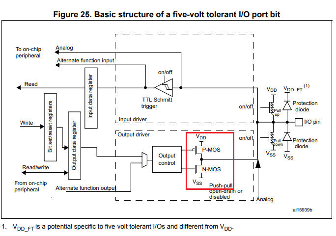
You can see 2 MOSFET transistors that appear after the Output control box.
The top MOSFET is a P-MOS MOSFET transistor.
The bottom MOSFET is a N-MOS MOSFET transistor.
P-MOS and N-MOS transistor work inversely to each other with this setup.
When a 1 is fed into this transistor configuration, the NMOS transistor turns on (the P-MOS is off) . Notice how this NMOS transistor is connected to VSS, or GND. This pulls the output load connected to the I/O pin to GND; thus, it will be OFF. So with a 1 or a logic HIGH state arriving at this transistor configuration, the load will be off. Current will be sinked down to ground.
When a 0 is fed into this transistor configuration, the PMOS transistor turns on (the N-MOS is off). Current is sourced from the P-MOS transistor to the I/O output pin and the load is turned on (that is, if the current is sufficient to power on the load).
This configuration gives us an output configuration that produces a LOW state or a HIGH state.
Push-pull configuration, again, is the default setup in an STM32 program.
It is the ideal configuration for powering digital devices, because it gives either an ON state or an OFF state.
Open-drain configuration, again, has more to do with communicating via serial communication protocols
such as I2C than with powering digital devices.
So this is how push-pull output configuration works in an STM32 microcontroller
board.
Related Resources