
What is the Role of the ROM Boot Loader in Booting Embedded Linux in a Beaglebone Board?
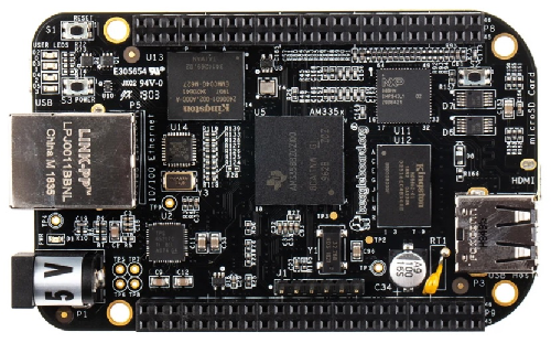
So a beaglebone board is an embedded microcontroller which can run the Linux operating system.
However, in order to do this, we need several software components to be in place to make this happen.
The first part of the equation necessary would be the ROM Boot Loader (RBL).
The ROM boot loader is the very first piece of code to run on the System on Chip (the beaglebone) when power is supplied to the board.
The ROM boot loader has several important jobs that it accomplishes to making ulimately running linux on the beaglebone board possible.
From supplying power to the board, the RBL is the very first component that is run.
The diagram shows this.
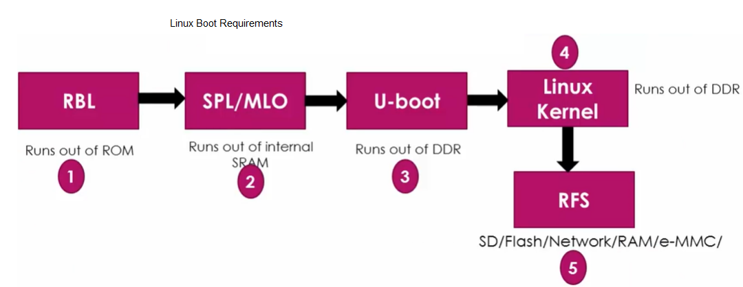
You can see the RBL is the first component.
So now let's go over all the jobs that the RBL accomplishes to make running an operating system like linux possible.
Before we do this, let's go over the block diagram of the processor of the BeagleBone black board.
So the processor for a BeagleBone black board is the ARM Cortex-A8 processor.
This is important to know because this holds the ROM memory, which contains the ROM bootloader software.
The diagram of the ARM Cortex-A8 processor is shown below.
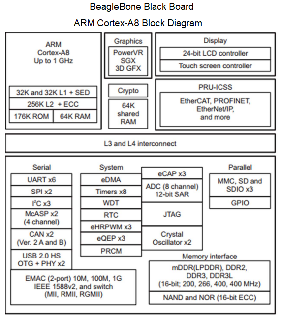
So you can see that the ROM memory space in an AM335x ARM cortex-A8 processor is 176KB.
This is also reflected in the datasheet for the processor.
This is shown below.
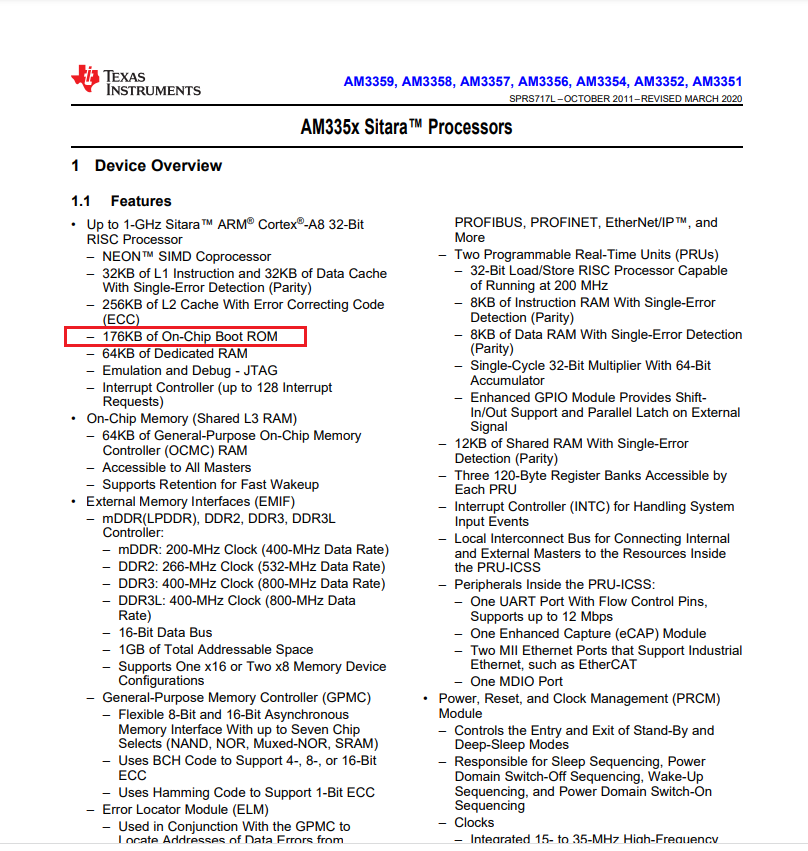
You can see that the AM335x processors provide 176KB ROM memory from which a ROM bootloader software can operate.
Later in this article, you will also see how the RAM plays in.
The ROM serves to store the RBL software that is needed for the booting process to start.
Later the second stage boot loader will be loaded into the RAM of this processor, so it can then load in the third stage boot loader, which loads in the linux kernel.
You can see in the block diagram that there is 64k RAM with an additional 64K shared RAM for a a total space of 128KB RAM.
We will get to this more later.
Next we go over something called the ROM code startup sequence, which is shown in the
diagram below.
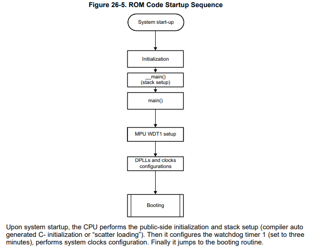
This shows the steps that the CPU takes in the booting process.
First, the system starts up. Then the ROM provides an initialization procedure. A watchdog timer is then run. If the CPU can't boot the linux kernel from the ROM within 3 minutes, the watchdog timer will then restart the whole procedure again. So there is a 3-minute period by which the booting must be successful, or else there will automatically be a restart from the beginning.
After the watchdog timer starts, the next step is the configuration of the clocks on the system on chip. All of the clocks work through the PLL, or phase locked loop. This is a clock system in which the original signal can be multiplied to feed clock signals of higher frequency to power other components on the chip. This clock signal is usually derived from a crystal oscillator or an RC oscillator. It powers components such as the processor, the display subsystem, the USB subsystem, etc.
The BeagleBone black board uses a 24MHz crystal oscillator, which in a PLL clock system, can produce a frequency up to 960MHz to power other components. That's the power of PLLs.
According to the datasheet for the AM335x ARM cortex-A8 microprocessors, "the ROM code configures the clocks and DPLLs which are necessary for ROM code execution." The MPU ADPLLS provides 500MHz for the cortex-A8 processor. So the ROM code initializes all the clock configures all the clocks needed to execute the ROM code, including providing 500MHz to the A8 processor.
There's a table in the datasheet that shows all of the ROM code default clock settings that are done in the clock configuration process.
This table is shown below.
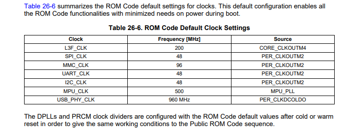
By default, the L3F clock is run at 200MHz, the SPI clock at 48MHz, the MMC clock at 96MHz, the UART clock at 48MHz, the I2C clock at 48MHz, the MPU clock at 500MHz, and the USB clock at 960MHz.
These values cannot be changed because in the ROM code because ROM is read-only memory. However, you can adjust clock values after the second stage program boot loader is loaded in the RAM.
After the clock configuration, the RBL then goes to the booting process. So now the RBL wants to fetch the second stage boot loader from the devices list as per the value of SYSBOOT[4:0].
This is shown in the diagram below.
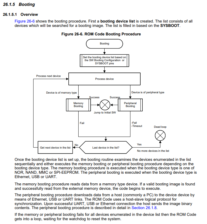
The RBL copies the SPL/MLO from the memory device into internal SRAM.
The SPL and the MLO are almost the same except the fact that, MLO has a header which contains some information like load address, size of the image, etc.
the RBL will then execute this code now in the internal SRAM of the SOC.
In summary, the ROM boot loader (RBL) implements the stack setup, watchdog timer 1 configuration (set to 3 minutes timeout), system clock configuration using the PLL clock source, searches memory devices or other bootable interfaces for MLO or SPL, copies the MLO or SPL into the internal SRAM of the chip, and then executes the MLO or SPL.
This then concludes the job or role of the RBL.
The second stage boot loader then takes over.
This is the role of a ROM boot loader for booting embedded
linux in a BeagleBone board.
Related Resources