
How to Read Input from an MCP230xx I/O Port Expander Connected to an Arduino
In this project, we will show how to read input from input devices connected to an MCP230xx I/O port expander connected to an arduino microcontroller.
An I/O port expander is a chip that allows additional I/O ports to a microcontroller.
So if you're running out of I/O ports on a microcontroller, it's a very useful way of getting additional inputs or outputs to a circuit.
We have shown already in previous circuits how to work with I/O ports to turn on output devices with the MCP23008 circuit and the MCP23017 circuit.
However, we haven't gone over a circuit on how to read data from input devices.
In this circuit, we will connect 3 pushbuttons to 3 of the I/O ports and read whether the pushbutton is reading a HIGH voltage (in which it's pressed down) or a LOW voltage (in which it's unpressed). When a pushbutton is pressed, its corresponding LED will light up. When the pushbutton isn't pressed, its corresponding LED will be off.
This circuit will fully demonstrate how to read input from I/O port expanders.
Components Needed
- MCP23008 I/O Port Expander
- 3 220Ω resistors
- 3 1KΩ resistors
- Red LED
- Green LED
- Yellow LED
- 3 Pushbuttons
- Arduino microcontroller
The MCP23008 I/O port expander can be obtained for a little over $2.
It is a perfect addition to a microcontroller where more I/O ports are needed.
It is a 18-pin chip.
The datasheet for this chip can be found at the following link: MCP23008 Datasheet.
The pinout of the MCP23008 is shown below.
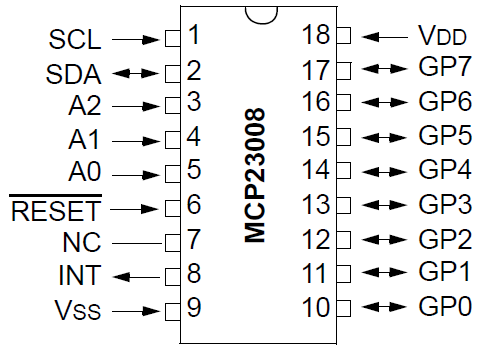
The MCP23008 can be powered with +5V. Therefore, we can connect VDD to the 5V terminal of the arduino. We connect VSS to ground. This completes the powering that's necessary for the MCP23008.
The GP0-GP7 are the 8 I/O ports.
NC is Not Connected so we leave that pin unconnected (or floating).
SCL is the serial clock line. It connects to analog pin 5 on the arduino, which is the analog clock pin.
SDA is the serial data line. It connects to analog pin 4 on the arduino, which is the analog data line.
INT is the interrupt pin for the outputs. Being that we are not going to use interrupts here, we just leave this pin unconnected.
The
A0, A1, and A2 are the address pins. You only need be concerned about these pins if you are using multiple
MCP23008 chips. These pins are externally biased, meaning you provide voltages to them to create different addresses. Since
there are 3 pins, you can create a total of 8 different addresses (23=8). This is only necessary if you are connecting
multiple ICs, so that we can distinguish between them. For example, if I grounded A2 and A1 and held A0 HIGH, this would create
the address 001. Being that we are grounding all 3 pins, the address will for the address pins will be 000. But if you are connecting
up to 8 MCP23008s, you will need to configure these pins so that each has a unique address: 000, 001, 010, 011, 100, 101, 110,
111. This way, you will be able to uniquely address each of them.
MCP23008 I/O Port Expander Circuit with an Arduino Microcontroller
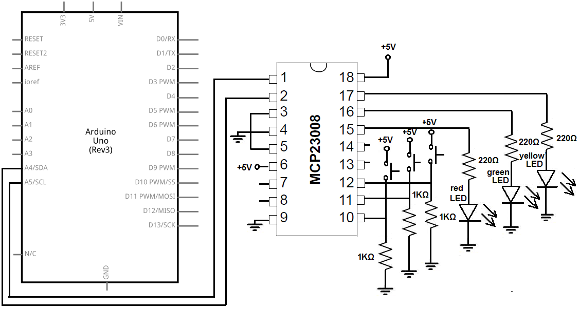
The MCP23008 I/O port expander circuit we will build with an Arduino microcontroller to read inputs from pushbuttons is shown below.
This circuit will have 3 pushbuttons on pins 10, 11, and 12.
Now, will explain the circuit hardware connections.
To the first 3 I/O pins, pins 10, 11, and 12, we connect pull-down resistors. Pull-down resistors are resistors which are normally LOW but become HIGH when pressed down. So with our circuit, when the pushbuttons are not pressed, the pin is in a LOW logic state. when we press down on the pushbutton, the state becomes HIGH. So, once again, all the buttons unpressed, the arduino will read all 0s. Once pressed, the arduino will read a 1 for whatever button is pressed.
The last 3 I/O pins, pins 15 , 16, and 17, we connect an LED to with a series-limiting resistor to make sure too much current doesn't blow out the LED. To pin 15, we place a red LED. To pin 16, we place a green LED. And to pin 17, we place a yellow LED.
The LEDs correspond to the pushbuttons.
The first pushbutton (on pin 10) corresponds to the red LED (on pin 15).
The second pushbutton (on pin 11) corresponds to the green LED (on pin 16).
The third pushbutton (on pin 12) corresponds to the yellow LED (on pin 17).
So if you press down on a certain pushbutton, that LED will light up.
You can also press multiple pusbuttons at once and the multiple corresponding LEDs will light up.
To power the pin, we attach +5V to VDD and connect VSS to GND. This establishes power to the MCP23008 chip.
We leave the NC (Not Connect) pin unconnected (or floating).
We connect pin 1 of the MCP23008, which is SCL (serial clock line) to analog pin 5 of the arduino. This allows for clock synchrony between the arduino and the I/O port expander chip.
We connect pin 2 of the MCP23008, which is the SDA (serial data line) to analog pin 4 of the arduino. This allows data transfer between the arduino and the I/O port expander chip.
Being that we're not working with interrupts, we leave INT pin unconnected.
Being that we don't want to use the
And we connect the address pins, pins A0, A1, and A2,
to ground. This makes the address of these 3 pins 000.
Later on in our code, this will be important for addressing this MCP23008 chip.
Code
The code so that we can connect an MCP23008 I/O port expander to an arduino microcontroller to read inputs from 3 pushbuttons on pins 10, 11, and 12, while lighting up corresponding LEDs on pins 15, 16, and 17 when pressed is shown below.
Arduino's I2C communication library is called the Wire library. With this library, you can easily write to and read from I2C devices.
#include <Wire.h>
byte inputs=0;
void setup()
{
Wire.begin();
Wire.beginTransmission(0x20);
Wire.write(0x00);
Wire.write(00000111);
Wire.endTransmission();
}
void loop()
{
Wire.beginTransmission(0x20);
Wire.write(0x09);
Wire.endTransmission();
Wire.requestFrom(0x20, 1);
inputs=Wire.read();
if (inputs == 0){
Wire.beginTransmission(0x20);
Wire.write(0x09);
Wire.write(00000000);
Wire.endTransmission();
}
if (inputs == 1){
Wire.beginTransmission(0x20);
Wire.write(0x09);
Wire.write(001000000);
Wire.endTransmission();
}
if (inputs == 2){
Wire.beginTransmission(0x20);
Wire.write(0x09);
Wire.write(010000000);
Wire.endTransmission();
}
if (inputs == 3){
Wire.beginTransmission(0x20);
Wire.write(0x09);
Wire.write(011000000);
Wire.endTransmission();
}
if (inputs == 4){
Wire.beginTransmission(0x20);
Wire.write(0x09);
Wire.write(10000000);
Wire.endTransmission();
}
if (inputs == 5){
Wire.beginTransmission(0x20);
Wire.write(0x09);
Wire.write(10100000);
Wire.endTransmission();
}
if (inputs == 6){
Wire.beginTransmission(0x20);
Wire.write(0x09);
Wire.write(11000000);
Wire.endTransmission();
}
if (inputs == 7){
Wire.beginTransmission(0x20);
Wire.write(0x09);
Wire.write(11100000);
Wire.endTransmission();
}
}
First, we import the Wire library, which is the library for communicating with I2C devices.
In our setup() function, we create a Wire object to initiate the process of communication. Without this, we can't communicate with the target device. We then begin transmission by the line, Wire.beginTransmission(0x20). The MCP230xx line of I/O port expanders have a base address of 0x20 + A address. In our case, since we grounded all the address pins, our address pins had the value 000. So 0x20 + 000= 0x20. This is why our final address is 0x20. However, if our address pins had a different value, our address would be different. If we connected all the address pins (A0, A1, A2) to +5V, then the address pins would have a value of 111, which in decimal or hexadecimal is 7. Then, our address would have been 0x27 (since 0x20 + 7 = 0x27). So this is an important concept to know, because without the correct address, you won't be able to initiate communication with the target MCP230xx devie.
Then we select the IODIR register. The address for this register is 0x00. This can be found in the datasheet. All the addresses of registers that we need for programming can be found in the MCP23008 datasheet. The IODIR is the register of all the 8 pins in port A. The next line then sets all the first 3 pins to inputs and the rest of the pins as outputs. This is why we give the value, 11100000, to the IODIR.
Next is our loop function which repeats over and over again. Here we will write which pins are on and which are off.
First, we begin communication with the MCP23008 chip, which always must be done. Then we write the line, Wire.write(0x09). This selects the GPIO pins, which are the I/O pins. We request a byte from this MCP23008 from the GPIO pins. This byte represents the value of the GPIO pins. We read this value into the inputs variable. The difference between IODIR and GPIO is that IODIR only can control whether a pin is input or output. GPIO doesn't control that but now controls whether that pin turns on or off. Writing a 1 to the pin turns it on, while writing a 0 turns it off. Here, we select the GPIO register and then write the value in binary so you can see the exact bits which are on and off.
So now we have the value read in from the GPIO pins of the MCP23008. Because only the first 3 pins are inputs, those are the only pins which will vary in value. Because it is pins, there are a total of 8 different values (since 23=8). The values can either be 000, 001, 010, 011, 100, 101, 110, or 111. Pin 0 represents the first bit. Pin 1 represents the second bit. Pin 3 represents the third bit. The first pushbutton (on pin 0) correlates with the red LED on pin 6. The second pushbutton correlates with the green LED on pin 7. The third pushbutton correlates with the yellow LED on pin 8. So for example, if we push down on the first pushbutton, the red LED will light up. If we push down on the second and third pushbuttons simultaneously, the green and yellow LEDs turn on.
In this circuit, in order to correlate the pushbuttons which are pressed, we use a series of if statements which cover every possible combination. So there are 8 if statements in total.
If the value of the inputs variable is 0, then we know that none of the pushbuttons are pressed. In this case, all the outputs are off, so we write the value of 00000000 to the GPIO register.
If the value of the inputs variable is 1, then we know that the first pushbutton only has been pressed.
If the value of inputs is 2, then we know that the second pushbutton only has been pressed.
If the value of inputs is 3, then we know that the first and second pushbuttons have been pressed.
If the value of inputs is 4, then we know that the fourth pushbutton has been pressed.
If the value of inputs is 5, then we know that the first and third pushbuttons have been pressed.
If the value of inputs is 6, then we know that the second and third pushbuttons have been pressed.
If the value of inputs is 7, then we know that all 3 pushbuttons have been pressed.
For each of these values, we turn on the corresponding LEDs.
And this is how we can read values from a MCP230xx I/O port expander IC.
Feel free to add your variations to this circuit.
Related Resources
How to Connect an MCP23017 I/O Port Expander to an Arduino Microcontroller