
Requirements to Boot Linux on a Beaglebone Board
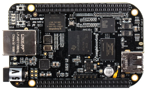
So a beaglebone board is an embedded microcontroller which can run the Linux operating system.
However, in order to do this, we need several software components to be in place to make this happen.
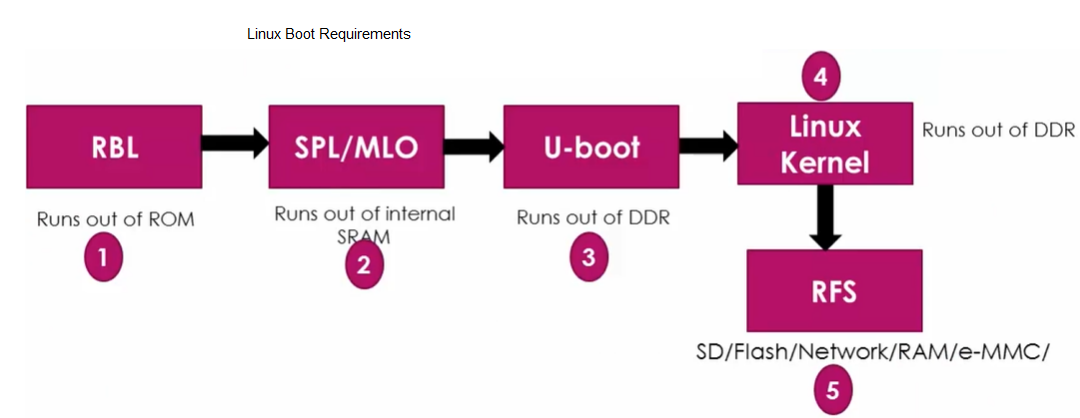
The first part of the equation necessary would be the ROM Boot Loader (RBL).
The ROM boot loader is the very first piece of code to run on the System on Chip (the beaglebone) when power is supplied to the board.
The major job of the ROM boot loader is to load and run the second stage boot loader, such as the SPL (Secondary Program Loader) or MLO (Memory Loader). The second stage boot loader loads out of internal SRAM memory.
The job of the second stage boot loader is to load and execute the third stage boot loader such as U-boot.
The job of the third stage boot loader is to load and run the Linux kernel. This is run from DDR SDRAM memory.
The last part needed is the root file system (RFS), which can be SD, Flash, etc.
The diagram which illustrates all these needed parts for the linux kernel to be able to be run on a beaglebone board is shown below.
Beaglebone Board boot options include NAND Flash, NOR Flash, USB, eMMC, SD card, Ethernet, UART, and SPI.
This means that you can have the boot images in any of the above memory or peripheral devices and boot the linux kernel from any of them.
Just like a regular computer, we can have multiple devices on the system and then boot from whichever device we preference in a given boot order. For example, with a computer, you can boot first from a CD ROM; if that fails, we may then specify the next device to boot from as the USB drive.
The SYSBOOT is one of the registers of the SOC and its first 5 bits determines the boot order for the system.
The SYSBOOT[4:0] value of 00000b is reserved and cannot be used.
The SYSBOOT[4:0] value of 00001b means the SOC will try to boot first from UART0. If that fails, it will try to boot from XIP (eXutable in Place memory like NOR Flash). If that fails, it will then go on to try and boot from MMC0. If that fails, then it will lastly attempt SPI0. If that fails, then an error message will occur showing unsuccessfully booting of the system.
This is shown in the table of the SYSBOOT Configuration pins below.
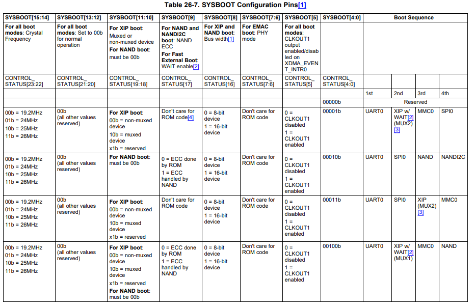
See there's a whole bunch of sequences you can choose from based on the number specified for the SYSBOOT[4:0] pins.
The table is not complete, as there is continuation that shows other devices that can be booted first.
To see all the tables for the SYSBOOT configuration pins, see the datasheet at the following link: AM335x ARM Cortex A8 Microprocessors Technical Reference Manual.
So let's now go over the whole process again.
So let's go over what happens when you reset a system. What happens first?
So the first thing that occurs when you reset the SOC, the code stored in the ROM runs first.
The code stored in the ROM is called the ROM boot loader. This code is programmed into the ROM of the SOC during the fabrication process. The ROM cannot be written to, as this is read only memory.
The job of the ROM is to set up the SOC clock, watch dog timer, etc. and also to load the second stage boot loader, usch as the MLO or SPL.
After the second stage boot loader, the SOC decides where to boot from by reading the register SYSBOOT register. The value of the SYSBOOT[4:0] determines the booting device list, as we previously went over. The voltage level on the SYSBOOT pins determines the pin values of the 16 pins of the SYSBOOT register.
If the SOC can successfully boot from one of the devices on the
booting list, then the linux kernel will start successfully.
Related Resources