How to Build a Rotary Encoder Circuit with an Arduino
In this project, we are going to build a circuit which uses a rotary encoder.
A rotary encoder is a device which allows us to know whether a knob is being turned clockwise or counterwise (which is one way or the other).
It can know when a user is turning the knob one way versus turning the knob the other way. Therefore, based on which way the user turns the knob, we can know this and perform any circuit action based on the directional change.
In this circuit, we will control demonstrate the use of a rotary encoder and show how it detects clockwise rotation versus counterclockwise rotation. In our software code,
we will calculate the angle degrees that the rotary encoder is in at a given moment. So if the rotary encoder is being turned one way, the angle degrees will start at 0 and go up in increments
to 360 degrees and back to 0 and then back to positive degrees. If the encoder is being turned the other way, the angle degrees will start at 0 and go down to -360 degrees and then back to 0 and then to the negative values again.
Thus, rotary encoders allow for pretty dynamic intervention.
Components
- Rotary Encoder
- Arduino
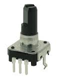
The rotary encoder we will use is a 5-pin device.
However, in this circuit we will only use 3 of the pins.
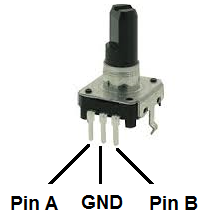
The 3 pins we will use are the 3 pins in front. These pins are Pin A, Pin B, and Ground. Below is the pinout diagram.
Below is the graph of the pulses given out from
the rotary encoder Pin A and Pin B.
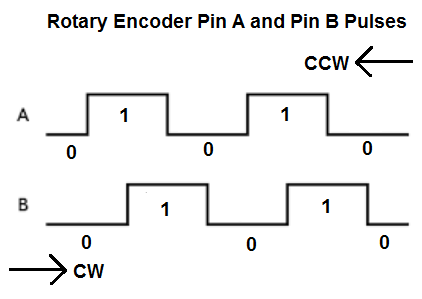
Based on this graph above, we when the rotary encoder is being turned clockwise, the graph from above presents from left to right. When the encoder is being turned counterclockwise, the graph from above presents from right to left.
Below are the values that result from clockwise and
counterclockwise rotation.
| Rotary Encoder Clockwise Rotation | |||
| A | B | A | B |
| 0 | 0 | 1 | 0 |
| 1 | 0 | 1 | 1 |
| 1 | 1 | 0 | 1 |
| 0 | 1 | 0 | 0 |
| Rotary Encoder Counterclockwise Rotation | |||
| A | B | A | B |
| 0 | 0 | 0 | 1 |
| 0 | 1 | 1 | 1 |
| 1 | 1 | 1 | 0 |
| 1 | 0 | 0 | 0 |
The rotary encoder knows which way the knob is
being rotated by the consecutive values which occur.
If the values go from 00 to 10 to 11 to 01 to 00, then the knob is
being turned clockwise. If the values go from 00 to 01 to 11 to 10
to 00, then the knob is being turned counterclockwise. This is how
the encoder knows. We can put
if statements in our code to see what values are going
from what to what.
This is how we can tell the rotational way that the knob is turning.
Rotary Encoder Circuit
The rotary encoder circuit we will build with
an Arduino is shown below.

This above circuit built on a breadboard is shown below.
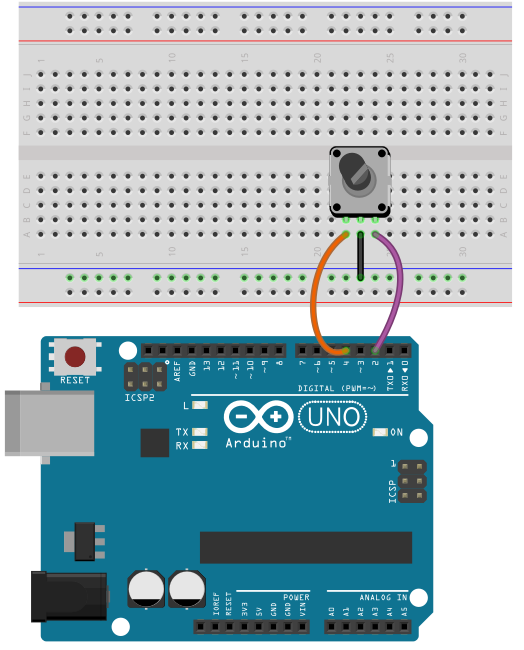
With these connections, we have all the hardware connections. Now all we need is the software to get this circuit operating.
Code
The code needed to display the time that is currently recorded by the real-time clock module.
const int encoderPinA= 4;
const int encoderPinB= 2;
int angle=0;
int encoderPos=0;
int encoderStepsPerRevolution= 16;
boolean encoderALast= LOW;
void setup() {
pinMode(encoderPinA, INPUT);
pinMode(encoderPinB, INPUT);
digitalWrite(encoderPinA, HIGH);
digitalWrite(encoderPinB, HIGH);
Serial.begin(9600);
}
void loop(){
boolean encoderA= digitalRead(encoderPinA);
if ((encoderALast == HIGH) && (encoderA == LOW))
{
if (digitalRead(encoderPinB) == LOW)
{
encoderPos--;
}
else
{
encoderPos++;
}
angle= (encoderPos % encoderStepsPerRevolution) * 360/encoderStepsPerRevolution;
Serial.print(encoderPos);
Serial.print(" ");
Serial.println(angle);
}
encoderALast= encoderA;
}
This is the code needed to show the position of the encoder and the angle of the encoder.
By position, this is what's meant. When we first start the code and have the Serial Monitor up, we position begins at 0. If we turn the knob clockwise one increment over, the position goes to 1. If we turn it again clockwise, the position is now 2 and it goes up in increments of 1 for each slight turn we make. If we turn turn the knob counterclockwise, this position will decrement by 1. So, for example, if we were at position 10, which means we made 10 clockwise rotations, and then we go counterclockwise, the position will now be decremented by 1 to 9. So this is the position.
The angle now represents a full 360 degrees rotation. Since there are about 16 rotations per full 360 degree rotations, each rotation increases or decreases the angle by about 22
degrees. So you will for example, see angle changes from 0 to 22 to 45 to 67 to 90 etc for clockwise rotation and from 0 to -22 tp -45 to -67 to -90 for counterclockwise rotation.
So this is an example of a rotary encoder circuit. This
code can be made to be very dynamic. We can add output devices to this circuit so that we can turn a certain device or devices when there is counterclockwise rotation and turn on
another device during clockwise rotation. Being that the code can detect which way the rotary encoder is moving, there is limitless options to what we can do in a circuit.
Related Resources
How to Build a Real-time Clock Circuit with a DS1307 Chip