How to Build a Very Basic SCR Circuit
In this article, we will go over how to connect an SCR to a circuit to build many different types of useful circuits with them.
SCRs are devices that once they are triggered on, they stay on. This means they are a latching circuit,
meaning once they are
triggered (or latched on), they stay on unless the power going to the anode is shut off. Being that they operate like this,
they are very useful and widely used for alarm circuits such as fire and burglar alarms.
Basics of SCRs
Before we actually go over how to build the circuit, we will first explain SCRs in detail to gain better understanding of how they're connected in a circuit and what they can do.
A silicon-controlled rectifier (or SCR) is a latching switch that once triggered, stays latched on. It is also referred to as a triac. Because once it is triggered, it stays on, it is used many times as a basic omponent in fire alarms and burglar alarms.
An SCR is a 3-pin device. One pin is the gate terminal and the other 2 are the anode and cathode terminals. The anode is the terminal that receives positive voltage and cathode connects to the negative voltage or ground of the circuit.
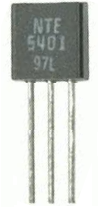
Below is the pinout of the C106B triac:
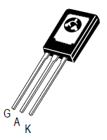
Looking at the above SCR, with it turned to its back surface, the pin to the leftmost is the gate terminal, the middle pin is the anode, and the rightmost pin is its cathode.
The gate terminal is the terminal which receives the trigger voltage so that the SCR can turn on. The anode terminal receives the positive DC voltage and usually the load which you want the SCR to power. And the cathode terminal connects to the negative voltage or ground of the power source.
Like a transistor, when the SCR receives sufficient voltage at its gate terminal, it conducts across from anode to cathode. Without this voltage at its gate, no current can flow from anode to cathode. This voltage is referred to as the gate trigger voltage. If you want to know what amount of voltage is needed to turn the trigger on the SCR, refer to this on the SCR's datasheet. This is the voltage you must apply for conduction to occur from anode to cathode. There is also a gate trigger current, which is the amount of current which the gate terminal needs to turn. Both the voltage and current must meet these amounts for the SCR to turn on.
Unlike a transistor, though, a SCR is different in that once it receives sufficient voltage at its gate, it conducts indefinitely from anode to cathode- unless power is disconnected from the anode. So while a transistor needs ongoing current at its base or gate terminal to conduct current across its junction, an SCR only needs to be triggered once to remain on. Thus, it acts like a latching circuit in that once it is turned on, it latches on and stays on.
This is the datasheet for the C106B: C106B SCR Datasheet.
How to Build a Basic SCR Circuit
So now that we know the pinout of an SCR and what each pin represents, we can now connect it to build a circuit.
We will build a circuit that turns on a buzzer when a pushbutton is pressed. Once pressed, the buzzer will remain on unless the power feeding it
is disconnected.
Parts Needed
- C106B SCR
- Normally Open Pushbutton
- 100Ω Resistor
- 3 AA Batteries
- 3V buzzer
1 'AA' battery will act as the 1.5V power source on the left.
The other 2 'AA' batteries placed in series will be 3V. This voltage will power the buzzer on the anode side of the SCR.
The 100Ω resistor just acts an attenuator to dampen the voltage to protect the gate terminal of the SCR from being exposed to too much power, which could damage it.
In this case, we use a 3V buzzer. If you don't have a voltage which operates off of 3V, then just use a higher voltage-rated one. But you will have to increase the DC voltage used to power it, which means you will have to use more batteries.
SCR Circuit
The circuit which we will build is shown below:
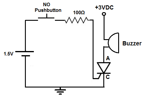
The 1.5V which will act as the gate trigger voltage will trigger the SCR to turn on once the pushbutton is closed. The pushbutton is normally open. Only when the button is closed does the SCR get triggered on. Once pushed down, the SCR receives sufficient voltage and current now begins to flow from anode to cathode. At this point in stage, the buzzer gets turned on and it stays on. Even if you let go of the pushbutton and the pushbutton is now open again, the buzzer will still remain on. This is what is meant by an SCR being a latching switch. Once triggered on by sufficient power to the gate, it will remain on. Only if the 3V of power is removed from the anode does the buzzer turn off. That's the only way to shut off the buzzer.
And this is the basics of how SCRs are connected and operate in a circuit.