
How the SPI Communication Protocol Works
In this article, we explain how the SPI communication protocol works.
The SPI communication protocol is synchronous and full-duplex communication between a master and either one or several slave devices.
It is synchronous because it uses a clock to synchronous output values.
It is full-duplex because communication can occur, at any given time, both ways, either from the master to the slave or the slave to the master. Also either device, the master to the slave, can both send and receive data simultaneously.
SPI is a 4-pin communication protocol system.
SPI uses 2 pins for data transfer- MOSI and MISO.
Remember that SPI communication, just like I2C communication, is always between a master and a slave.
MISO stands for Master In, Slave Out. This is the pin where the slave sends out data, which is then received by the master.
MOSI stands for Master Out, Slave In. This is the pin where the master sends out data, which then is received by the slave.
There is a SCLK pin, which gives the clock output, which functions to synchronize data transfer between the 2 devices.
Lastly, there is a SS (Slave Select) pin, which is used to enable or disable a slave device. If the SS is selected, the master can communicate with that specific slave. If it is not, the master cannot communicate with the device.
At any given time, only one slave device should be selected and the others off. A master cannot communicate with multiple slave devices at the same time.
Be aware that pins for SPI communication may go by different names other than MISO, MOSI, SCLK, and SS.
You may find SDO instead of MISO.
SDI instead of MOSI.
SCLK will be unchanged.
CE (chip enable) instead of SS.
When connecting 2 devices for SPI communication, the master and the slave, the 2 SCLK (or SCK) are connected together. Know that only the master device generates the clock signal. The slave device does not. This clock signal is used to synchronize data transfer.
The 2 MISO lines of each are connected together. If the pin is labeled SDO on the slave device, this connects to the MISO pin on the microcontroller.
The 2 MOSI lines of each are connected together. If the pin is labeled SDI on the slave device, this connects to the MOSI pin on the microcontroller.
The 2 SS lines of each are connected together. If the pin is labeled CE on the slave device, this connects to the SS or NSS pin on the microcontroller. NSS stands for negative slave select, meaning selected when active low.
Below is the diagram between a master and a slave device that shows the physical connections needed in order to establish
SPI communication between the devices.
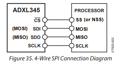
The example SPI connection above is from a master device (which is commonly a microcontroller) and an ADXL345 accelerometer (which is the slave device).
The only other hardware connections needed for the slave device is the power.
How SPI Communication Works
Now that we've gone over the physical connections needed to establish SPI communication, let's now go over how SPI communication works.
How does SPI communication work?
The SPI protocol works by starting a transaction, which is done by enabling the clock (SCLK or SCK). By enabling the clock, there is a clock signal which toggles from HIGH to LOW, HIGH to LOW
The master then sets the Slave Select (SS) line of the slave LOW (A transition from HIGH to LOW marks the selection of the particular slave, which stays in a LOW state during the whole process of transmission of data).
During the transfer of data, two shift registers of the same size are involved in transmission, one in the master and one in the slave. Data is usually shifted out with the most significant bit first, while shifting a new least-significant bit into the same register. At the same time, data from the slave is fhited into the least-significant bit of the register. Then the next subsequent bits are shifted. If more data needs to be exchanged after this, the shift registers will be reloaded and the process of exchange will start again.
When no more data needs to be transmitted, the master stops toggling the SCK line and it deselects the slave device by returning the SS line to a HIGH state.
Below are the waveforms depicting how SPI data transmission works.
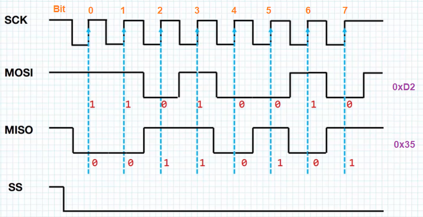
Notice how SCK is on, with a digital waveform of repeated cycles of ON-OFF signals.
Then notice how the Slave Select (SS) pin is pulled from a HIGH state to a LOW state, making the slave device selected and, thus, open for data transmission.
What is happening is MOSI and MISO data transmission are occurring together. Remember that SPI is full duplex method of communication, in which a master device can both send data to a slave and receive data from a slave simultaneously (a slave device does the same).
Within this example above, for MOSI, 11010010 is sent, which is 0xD2 in hex.
For MISO, 00110101 is sent, which is 0x35 in hex.
So this is the process by which the SPI communication protocol works in the general sense.
There are more advanced, in-detail features of SPI, but in general this is how the SPI communication protocol works.
Related Resources