
Rocker Switch Wiring
In this article, we will show how to wire a rocker switch to a circuit.
The rocker switch then can play a role as an on-off switch in the circuit so that it can turn on or turn off different devices in a circuit or the entire circuit itself.
Rocker switches are common components in many different types of electronic circuits that allow power to be turned on or off.
In this article, we will be demonstrating how to connect a SPST rocker switch.
Rocker Switch Internal Construction Diagram
We will now go over the wiring diagram of a rocker switch, so that you can know how rocker switches are internally constructed.
This will help you visualize how rocker switches work, so that you can know how to connect them.
Below is the internal construction of a SPST rocker switch:
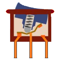
Based on this diagram above of the internal construction of a rocker switch, you can see that it can be in one of two states. It can be turned to one side or turned to the other.
This allows you to flip a device on or off. The metal bearing snaps down the switch so that it makes contact with one of two sides, depending on which side the switch is flipped to.
Rocker Switch Wiring Diagram
Now that you have an idea how rocker switches are constructed internally, let's go over the wiring diagram, so that you will now how to connect a rocker switch to a circuit.
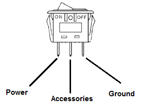
As shown below, rocker switches have 3 electrical connections.
The diagram below represents the schematic diagram for a SPST rocker switch:

Pin 1 is where the rocker switch receives the input power. Pin 2 is where the accessory that the switch is going to turn on is connected. Pin 3 is where the switch is either connected to ground or left open.
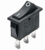
Below is a pictorial representation of the schematic diagram:
This translates into the following model in a real life rocker switch:
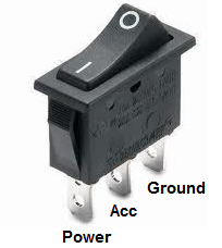
Below are the 3 pins that form electrical connection with a circuit, each described with their function in the circuit:
| Electrical
Connections |
Function |
| Power |
This
is the pin where the rocker switch receives its voltage. |
| Accessories |
This
is the pin that connects to the load of the circuit, whatever the
rocker switch turns on when it's switched on. Ex: lights, motor, etc. |
| Ground |
This
is the pin that connects to the ground of the circuit. |
Now these are the 3 pins which establish electrical connection to the circuit we are wiring the rocket switch to.
There is the pin which receives the power. There is the pin which connects to the load we are going to power. And there is the pin which connects to the ground of the circuit.
Example Rocker Switch Circuit
Now let's build an example rocker switch circuit, so that you can see how it works in a real-world practical example.
Let's take the circuit below:
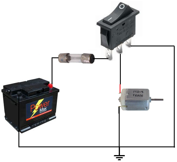
When the switch of the rocker switch is flipped to the ON position (to the left), the DC motor turns on and operates. When the switch is flipped OFF (to the right), the DC motor no longer receives power and flips off.
Many times with rocker switches, since they are only able to tolerate a certain amount of current, fuses are placed in between the power pin and the power source. This protects the rocker switch from receiving excess power, which could damage or destroy it.
You can see that the power pin (pin 1) receives the incoming power, which in this case is from a 12V battery. Pin 2 connects to the accessory or load which you want to power, which
in this case is a DC motor. And pin 3 connects to ground or is left open. This is when the DC motor is shut off.