
STM32F407G Microcontroller Bus Architecture- Explained

In this article, we explain the bus architecture of the STM32F407G microcontroller discovery board.
The bus architecture is an important part of a micrcontroller because the bus architecture is how the components in a micrcontroller communicate with each other.
An analogy is it is the highway of the microcontroller.
The bus system is the electrical pathway from the main processor to all of the various components of the microcontroller, such as the FLASH memory, the SRAM memory, the USB ports, the I/O ports, other electronic components on the board such as a camera, etc.
The processor is the heart of the microcontroller and it needs to have a bus system to communicate with all of the other parts of the microcontroller.
We will look at a few diagrams to see exactly the bus architecture of the STM32F407G microcontroller board.
The block diagram for the STM32F407G microcontroller board is shown below.
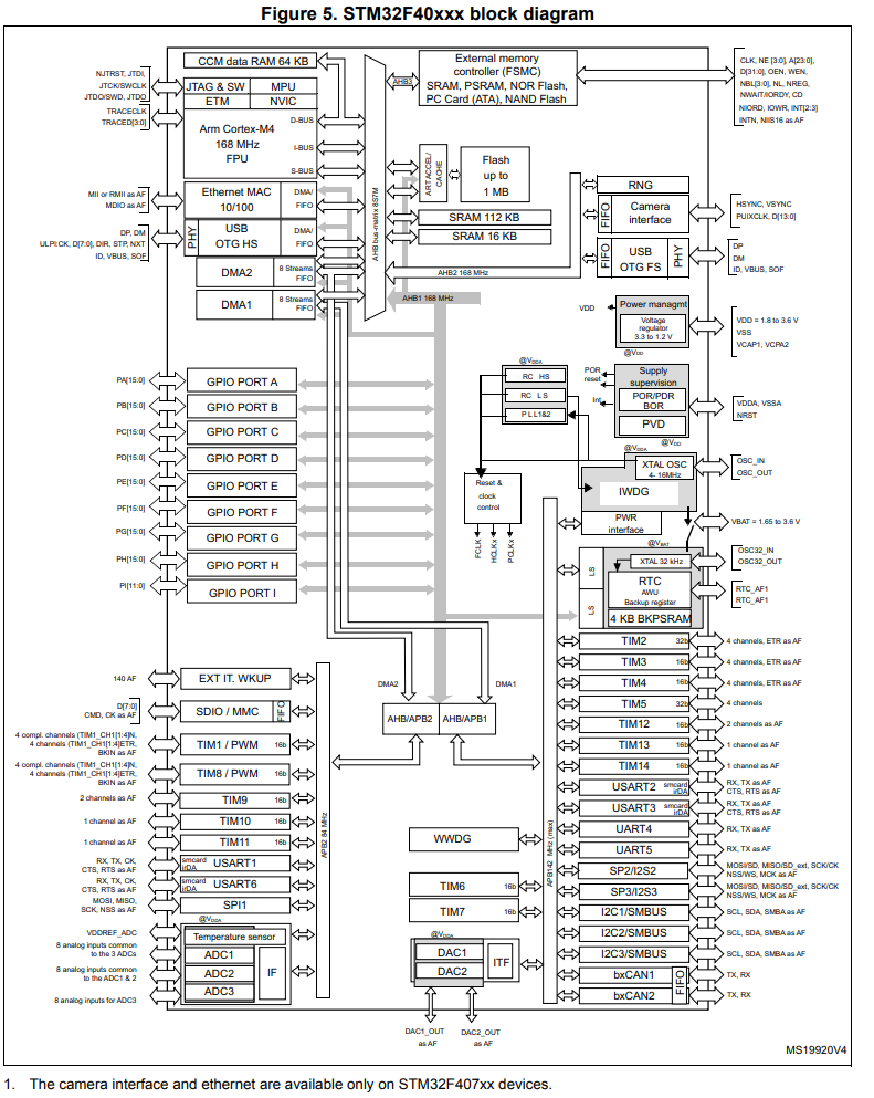
The STM32F407G microcontroller has an ARM Cortex-M4 processor, which you can see at the top left of the diagram.
This is the main heart or brains of the microcontroller.
This processor needs to communicate with all the rest of the components on the board. You can see there's a lot of memory such as Flash memory, SRAM, as well as the ability to connect external memory devices. There are I/O ports, such as the GPIO Ports. There are timers, connections for UART communication protocol, USART communication protocol, SPI communication protocol, and I2C communication protocol. There is also an onboard camera and many other components.
In order for the processor to be able to communicate with all these components, there must be a bus architecture system that provides electrical connection from the processor to the components. There is no wireless communication. It is done through physical electrical wiring via the bus system.
You can see three buses connected to the processor, which is the D-bus, the I-bus, and the S-bus. The D-bus stands for the data bus, which is used to transmit data. The I-bus stands for the instruction bus, which is used to transmit instructions. The S-bus stands for the system bus, which can transmit either data or instructions.
Apart from just physical electrical connection between the processor and the components, it's important to know the bus architecture of a microcontroller well for other reasons.
Another reason is to know the maximum frequency allocation for particular bus.
Looking at the ARM processor, we see that it a maximum operational frequency of 168MHz.
So the buses directly connected to this processor can run as high as 168MHz in speed.
You can see this in the AHB bus-matrix and you can see this same frequency in the AHB1 and AHB2 buses.
You can see that this high-frequency buses feed components such as the USB OTG FS and the camera interface. This is designed as such by the microcontroller board designer because these devices need high-speed operations. USB needs fast speed to transmit data fast. Cameras are heavy-computational devices, so they need high-speed operation.
If you follow the bus down, you see that this AHB1 bus separates into 2 buses: APB1 and APB2.
The APB1 bus has a maximum frequency operation of 42 MHz. This bus connects to devices such as timers, USART pins, SPI pins, I2C pins, and CAN pins.
The APB2 bus has a maximum frequency operation of 84 MHz. This bus connects to devices such as timers, USART pins, ADC pins, and PWM pins.
So knowing the bus architecture is important because it can let you know the maximum operating frequency for all the pins you may use on the board.
Instead of having to look at the block diagram for the microcontroller, the datasheet provides the system architecture diagram for the microcontroller.
This is shown below.
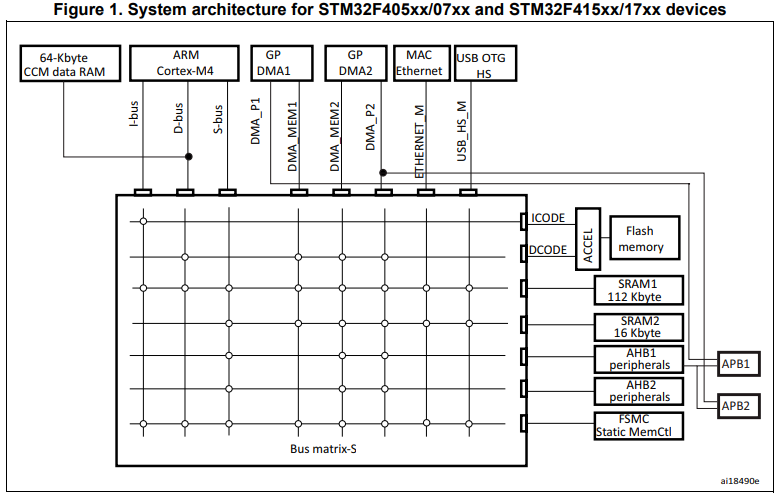
So using this diagram, we cna see exactly which bus makes connection with which elements. The elements across the horizontal top are the master devices. The element across the vertical right are the slave devices.
You can see based on this diagram that the ICODE and DCODE buses both go to Flash memory. It is important because it shows the functioning of a microcontroller. Being that it has an instruction bus and a data bus going to it, it shows that it can fetch instructions and data simultaneously.
If you look at the SRAM data, it has a single bus, the system bus, going to it that works with serialized data. Therefore, it can only fetch instructions or data at a single time but not both.
So studying the architecture bus can help you to understand the functioning of the microcontroller.
So another reason why it is important to be familiar with the
bus architecture is to know the general operation of the microcontroller.
Related Resources
How to Set Bits of a Number in C
How to Clear Bits of a Number in C