
Thermistor Temperature Sensor Circuit for a Battery Management System
In this article, we go over how to build a thermistor temperature sensor circuit for a battery management system.
We use a thermistor in a voltage divider circuit to determine the temperature of an external module such as a battery pack.
A thermistor is a variable resistor whose resistance varies in proportion to the temperature that the thermistor is exposed to.
There are 2 types of thermistors- NTC and PTC. The resistance of NTC thermistors vary inversely with temperature. The resistance of PTC thermistors vary directly with temperature.
NTC thermistors are the most commonly used type of thermistor, so this is what we will use in our circuit design. NTC thermistors are used in several different types of applications and can be seen in appliances such as ovens and fire detectors.
Thermistors are rated according to their resistance at a certain given temperature such as near room temperature such as 25°C.
When designing a thermistor voltage divider circuit, many elements need to considered.
First, you must consider the fixed resistor you must choose that forms the voltage divider circuit along with the thermistor.
A good way of selecting the value of the fixed resistor is to make it the same as the rated thermistor used.
For this circuit, we are using a 100KΩ NTC thermistor, so we will use a 100KΩ fixed resistor.
Usually thermistors are at their rated resistance at 25°C, which is more or less around room temperature.
So at room temperature, the NTC thermistor will output a resistance of 100KΩ and of course the fixed resistors will have a resistance of 100KΩ. Thus, if the voltage divider circuit has a supply voltage of 5V, then the voltage will divided roughly in half between the 2 resistors.
Thus, if the output voltage is about 2.5V, then we know the temperature is around 25°C, which is 77°F.
In fact, you can know the temperature based on the voltage output from the divider circuit.
NTC thermistors have a resistance inversely proportional to temperature. If the temperature is low, NTC thermistors offer a very high resistance. If the temperature is high, NTC thermistors have a very low resistance.
The datasheet for an NTC thermistor should have a Thermistor Output Table, which tells us the resistance that the thermistor will output at various given temperatures.
This is shown in the table below.
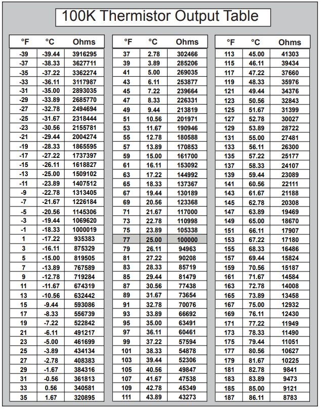
The complete datasheet for the 100K thermistor is shown in the following link: 100K Thermistor Datasheet.
You can see at the coldest extreme at -39°F or -39.44°C that the NTC thermistor outputs a resistance of 3916295Ω. At the total other extreme at the hottest temperature at 187°F or 86.11°C, the thermistor outputs a resistance of 8783Ω.
So during extremely cold conditions, in the voltage divider circuit, most of the supply voltage falls across the thermistor.
Doing the math, at -39°F or -39.44°C, 4.875V (5V(3.9M)/(3.9M + 100K)) would be dropped across the thermistor of the supplied 5V.
During extremely hot conditions, in the voltage divider circuit, most of the supply voltage falls across the 100KΩ fixed resistor.
Doing the math, at 187°F or 86.11°C, 0.37V (5V(8K)/(8K + 100K)) would be dropped across the thermistor of the supplied 5V.
The circuit for the thermistor temperature sensor is shown below.
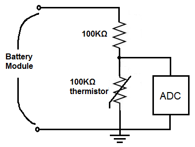
Now that we have the thermistor temperature sensor circuit, we need to connect to an ADC or microcontroller to read the voltage output. Then we can monitor the temperature of the battery module.
You may need to have a custom software program that has the
And this is how to create a thermistor temperature sensor circuit for a battery management
system to monitor the battery's temperature.
Related Resources