Timers/Counters of Embedded Microcontrollers- Explained
In this article, we go over what timers are, their purpose in embedded applications, and how to code them in C for embedded applications.
Timers/counters are probably the most commonly used complex peripheral in a microcontroller.
They are very versatile, being able to measure time periods, to determine pulse width, to measure speed, to measure frequency, or to provide output signals. Example applications might include measuring the rpm of a car's engine, timing an exact period of time, such as that necessary to time the speed of a bullet, producing tones to create music or to drive the spark ignition system of a car, or providing pulse-width or variable-frequency drive to control a motor's speed.
In this article, will discuss timers/counters in a generic sense and then more specifically, we will discuss timers/counters in AVR microcontrollers.
Although used in 2 distinctly different modes, timing and counting, timers/countesr are simply binary-up counters. When used in timing mode, the binary counters are counting time periods applied to their input, and in counter mode, they are counting the events or pulses or something of this nature. For instance, if the binary counters had 1-millisecond pulses as their input, a time period could be measured by starting the counter at the beginning of an event and stopping the counter at the end of the event. The ending count in the counter would bet he number of milliseconds that had elapsed during the event.
When a timer/counter is used as a counter, the events to be counted are applied to the input of the binary counter, and the number of events occurring are counted. For instance, the counter could be used to count the number of cans of peans coming down the assembly line by applying one pulse to the input of the counter for each can of peas. At any time, the counter could be read to determine how many cans of peas had gone down an assembly line.
The AVR microcontrollers provide both 8-bit and 16-bit timer/counters. In either case, an important issue for the program is to know when the counter reaches its maximum count and rolls over. In the case of an 8-bit counter, this occurs when the count reaches 255, in which case the next pulse will cause the counter to roll over to 0. In the case of the 16-bit counter, the same thing occurs at 65,535. The rollover events are extremely important for the program to be able to accurately read the results from a timer/counter. In fact, rollovers are so important that an interrupt is provided that will occur when a timer/counter rolls over.
Some AVR microcontrollers have 2 8-bit timers (typically, Timer 0 and Timer 2) and 1 16-bit timer ( typically, Timer 1), although this configuration will vary depending on the exact type of AVR being used.
We will now discuss timer prescalers and input selectors, features common to all of the timers.
Timer/Counter Prescalers and Input Selectors
Timer/counter units may use a variety of internal frequencies derived from the system clock as their input, or they may get their input from an external pin.
The timer counter control register (TCCRx) associated with the timer contains the counter select bits (CSx2, CSx1, CSx0) that control which input is used with a specific counter.
The figure below shows the prescaler and input selector configuration for a timer counter control registered, as used in most AVR microcontrollers.
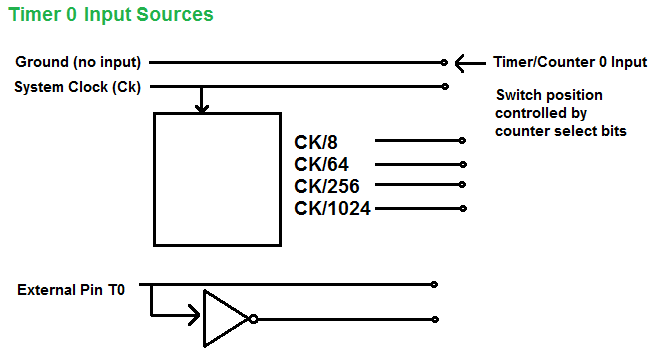
The timer has a system clock attached to it. Using the prescaler, it can then be scaled down to have a clock signal 1/8, 1/64, 1/256, or 1/1024 in size. The external pin
T0 can then determine if the timer counts falling edges or rising edges.
Timer 0
Timer 0 is typically an 8-bit timer, but this can vary according to the specific processor type. It is capable of the usual timer/counter functions but is most often used to create a time base or tick for the program.
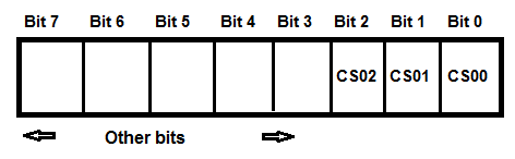
Timer counter control register 0, TCCR0, controls the function of Timer 0 by selecting the clock source applied to Timer 0.
The figure below shows the clock prescaler bit definitions for TCCR0. Other bits of TCCR0 control additional functions of Timer 0 in a manner similar to the control bits for Timer
1, which we will show later.
| CS02 | CS01 | CS00 | Interrupt Function |
| 0 | 0 | 0 | Stop,
Timer 0 is stopped |
| 0 | 0 | 1 | System Clock, CK |
| 0 | 1 | 0 | System clock/8, CK/8 |
| 0 | 1 | 1 | System Clock/64, CK/64 |
| 1 | 0 | 0 | System Clock/256, CK/256 |
| 1 | 0 | 1 | System Clock/1024, CK/1024 |
| 1 | 1 | 0 | External Pin T0, counts a falling edge |
| 1 | 1 | 1 | External Pin T0, counts a rising edge |
A program tick, like the tick of a clock, provides a highly accurate timing event.