How to Build a Touch On-Off Circuit with a 7414 Inverter Gate Chip
In this circuit, we will build a touch on-off switch circuit using a 7414 inverter chip.
This inverter gate chip circuit will function as a flip flop.
When we touch the touch wire, the LED turns on. And if we touch it again, the LED turns off.
This circuit truly functions as an on-off touch sensor circuit.
This is the same type of circuit we would see in a touch lamp, where you touch it on or off.
The main reason how this circuit can do this is through the use of a capacitor. In this circuit, we use 2 capacitors. When we touch the wire, we either charge up the capacitor or discharge the capacitor. Charging it up turns the LED off. And discharging the capacitor turns the LED on. We'll go over this in much more depth below.
We exploit NAND gate logic in order to make this circuit possible.
In this circuit, our output device will be an LED, which will turn on and off, as we touch the touch plate or touch wire.
Components
- 7414 Inverter Chip
- 4.7MΩ resistor
- 1MΩ resistor
- 470Ω resistor
- 1μF electrolytic capacitor
- 100nF ceramic capacitor
- Touch Plate
The 7414 hex inveter gate chip can be obtained very cheaply from a number of online retailers for just a few cents. One place it can be obtained from is Tayda Electronics at the following link: Tayda Electronics- 7414 Hex Inveter Gate IC. However, it is a very popular chip and many electronics parts suppliers have them.
The pinout of the 7414 is shown below, so that you can see how to
connect it in the circuit.
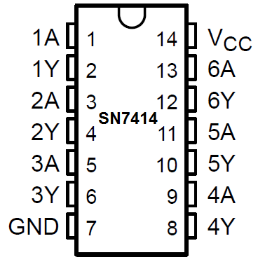
This inverter has 6 independent inverter gates.
The pins marked with A's are the inputs to the inverter gates and the pins marked with Y's are the outputs of the inverter gates.
The following chart shows inverter gate logic, which shows what output a
inverter gate chip will produce for a given input.
| Inverter Truth Table | |
| Input | Output |
| L | H |
| H | L |
This means that if the input is 0, the output will be 1 or HIGH. If the input is 1 or HIGH, the output will be 1 or LOW.
We will use this inverter logic as the basis for the function of our circuit.
Touch On-Off Circuit Using a 7414 Inverter Gate Chip
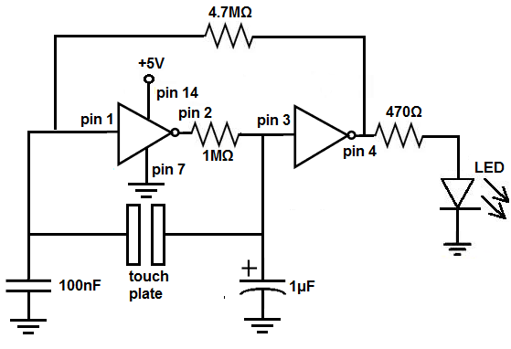
The touch on-off circuit we will build with a 7414 inverter gate chip is shown below.
To see this circuit diagram connection from the view of the integrated circuit (IC), see the following: Touch On-Off Circuit with a 4011 NAND Gate Chip shown from the IC
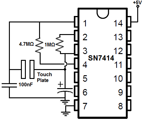
The breadboard schematic of the circuit above is shown below.
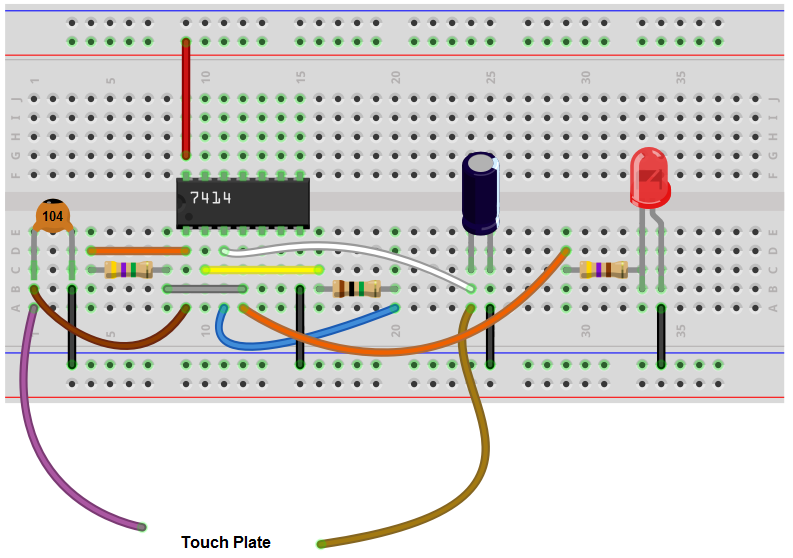
First, we must connect power to the 7414 inverter gate chip. We do this by connecting VCC, pin 14, to 5V and by connecting GND, pin 7, to power ground. This establishes power to the 7414 inveter gate chip.
We connect a 4.7MΩ resistor from pin 1 to pin 4.
We connect a 1MΩ resistor from pin 2 to pin 3.
In between pins 2 and 3, we connect a 1μF capacitor.
To pin 1, we connect a 100nF capacitor. In between these 2 capacitors, we place our touch plate or touch sensor wires. When touched, these wires allow for the output to switch either from HIGH to LOW or LOW to HIGH.
Lastly, we connect the output device that we want to turn on and off to pin 4, which is the output of the second gate, which is the total output of the circuit, since we're using 2 gates. The LED has a 470Ω current-limiting resistor to prevent the LED from blowing out due to excess current.
This completes all the hardware connections.
How the Circuit Works
This circuit is somewhat complex but still follows the simple principle of inverter gate logic. When the input to gate 1 is LOW, the output will be HIGH. So when the input to the first inverter gate is LOW, our output device, the LED, will be ON. When the 2 inputs are HIGH, the output will be LOW. So, in this case, the LED will be off.
The heart of our circuit which allows the flip flop ability is the 1MΩ resistor and the 1μF capacitor.
When the touch wires are touched, the 1μF capacitor either charges up to a voltage close in value to VCC or it discharges to near 0V.
When we charge up the capacitor, we charge up to near VCC. With the 1MΩ resistor, it pulls up the output of the output of gate 1 to VCC. This pulls the value of the output HIGH. Since the output of gate 1 is connected to the input of gate 2, this means that gate 2 receives a HIGH input. This makes the output LOW. Therefore, the LED will be off when the capacitor is charged.
Now when we touch the touch plate again, we discharge the capacitor. The capacitor's voltage plummets from near VCC almost to 0V. Now the output of gate 1 is 0V or LOW. This LOW signal is now fed into the input of gate 2, which will turn on the output, the LED.
The 100nF capacitor acts a second reserve to prevent the circuit from going on and off, on and off, repeatedly if we keep our hold on the touch plate. It keeps the signal either on or off once the touch plate is held. This prevents constant fluctuations of on and off.
And this is how this circuit works to mimic a flip flop, to function as a touch on-off circuit.
Related Resources
How to Build a Touch On-Off Circuit with a 4011 NAND Gate Chip
How to Build a Touch On-Off Circuit with a 4001 NOR Gate Chip
How to Build a Touch On-Off Circuit with a 4049 Inverter Gate Chip