How to Build a Touch Sensor Circuit with a Voltage Comparator

We've already shown how to build a touch sensor with a transistor in a previous project. Now, in this one, we will show how to build a touch sensor circuit using a LM393 voltage comparator.
A touch sensor circuit is a circuit which is activated when a user touches it.
Touch sensors are implemented into many electronic products, the most obvious example being a touch lamp, where the lamp turns on when a person touches the base of it.
In this circuit, we won't do anything too fancy but we will build make a touch sensor with a voltage comparator and leave out
2 jumper wires, which when touched will turn on our LED.
Components Needed
- LM393 voltage comparator Chip
- 4.7MΩ Resistor
- LED
- 330Ω Resistor
- 2 10KΩ resistors
- Jumper wires
Before we actually build our comparator circuit, we first must go over in detail the pinout of an LM393 comparator IC, so that you know what each pin is and what each pin does.
An LM393 is a 8-pin chip.
The pinout is shown below:
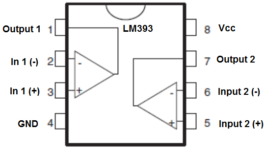
The LM393 has 2 power inputs. These are labeled Vcc and GND. Vcc is where the positive terminal of the voltage supply gets inserted into. This supply voltage can be as high as 36V. GND is where the ground wire of the voltage source gets connected to. These 2 terminals complete the power path for the LM393 chip and gives it the power it needs to function.
Apart from power, we now deal with the 2 operational amplifiers that are internally within the chip. Each op amp has 2 inputs and one output. These op amps are independent of each other, meaning each one acts independently to give its own output value (based on their 2 input values). In1 (-) and In2 (-) are the inputs for the op amp 1. Output 1 is the output of this op amp. In2 (-) and In2 (+) are the inputs for op amp 2. Output 2 is the output of this op amp.
For our circuit, we will only use one op amp; the other will be left unconnected.
Using both op amps is only needed when we deal with more complex circuits in which we need to monitor multiple levels. If we are only checking one level, then we need only one op amp.
Now that you know what each pin does, we will now explain how the chip works.
So, as explained, we have to give power to the chip in order for it to work. Once we have power to the chip, the next thing we must do is supply the op amp with 2 inputs for comparison, the 2 inputs whose voltage values we want to compare. After we have done this, we can now get an output. This output value will appear at the output terminal of the LM393.
If the voltage at the inverting terminal is greater than the voltage at the noninverting terminal, then the output of the op amp will be drawn up to Vcc. If the voltage at the inverting terminal is less than the noninverting, then the output of the op amp is drawn down to GND.
This means that when the inverting terminal voltage is greater, the load connected to output can be powered on. When the noninverting terminal voltage is greater, the load connected to output will be powered off. So if an LED is connected to output, it will turn on when the inverting voltage is greater and turn off when the noninverting voltage falls below the inverting voltage.
So now you know the basic pins that make up the LM393 and how it works. With this understanding, we can now build our circuit.
The other components we need are the LED and the 330Ω resistor in series to limit current to the LED so that it
doesn't burn out.
Touch Sensor Circuit Using a LM393 Voltage Comparator
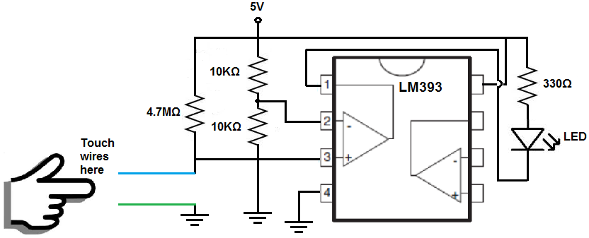
The schematic diagram of the touch sensor circuit using a LM393 voltage comparator chip is shown below.
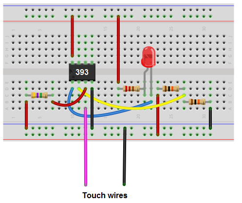
Below is the breadboard schematic version of the above circuit so that you can see the exact wiring of the circuit to the 4011 chip.
First and foremost, we must give power to the Lm393 chip. We will feed it 5V of power, so we give +5V to pin 8 and we connect pin 4 to GND. This establishes power to the chip.
How this circuit works is very basic.
The 4.7MΩ resistor connects to the non-inverting terminal of the op amp. This resistor pulls the voltage up so that the voltage is near 5V. It will be about 3.6V roughly.
The voltage divider circuit composed of 2 10KΩ resistors divides the 5V in half so that the voltage output will be about 2.5V. This connects into the inverting terminal of the op amp.
Thus, when the wires are not touched, the voltage at the noninverting terminal is greater than at the inverting terminal. Thus, the load, the LED, will be off.
However, when we touch the wires, our body resistance, which is about 10KΩ to 100KΩ, acts as a resistor. Our body acts as a resistor with the 4.7MΩ, forming a voltage divider circuit. Since our body has much less resistance than a 4.7MΩ resistor, very little voltage falls across us. Thus, there is little voltage drop across our bodies. When I tested the circuit with me touching the wires, the voltage was about 1.5V. So the voltage drops from about 3.6V to 1.5V when touched.
So when touched, the voltage is now greater at the inverting terminal than at the non-inverting terminal. Thus, the LED will now turn on and light up.
And this is how a touch sensor can be built with a voltage comparator chip.
Related Resources
How to Build a Touch Sensor Circuit with a NAND Gate Chip