
Transistor Biasing Methods
In this article, we will go over the different ways in which a bipolar junction transistor (BJT) can be biased so that it can produce a stable and accurate output signal.
Transistor biasing is the controlled amount of voltage and current that must be given to a transistor for it to produce the desired amplification or switching effect.
In other words, transistors must be fed the correct or appropriate levels of voltages and/or currents to their various regions in order to function properly and amplify signals to the correct level. This controlled amount of voltage and/or currents fed to the different junctions of a transistor is transistor biasing.
Without appropriate transistor biasing, the transistor may not function at all or amplify very poorly, such as
produce clipping of the signal or produce too low of gain. Therefore, it's very important that a transistor is biased correctly for it to produce
the intended output effect.
Base Bias
Base bias the simplest way to bias a BJT transistor. Base bias ensures that the voltage fed to the base, VBB, is the correct voltage, which then supplies the correct current so that the BJT has enough base current to switch the transistor on.
Below is a typical BJT receiving base bias:
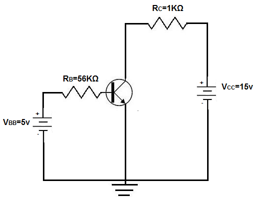
VBB is the base supply voltage, which is used to give the transistor sufficient current to turn the transistor on. RB is a resistance value that is used to provide the desired value of base current I B. VCC is the collector supply voltage, which is required for a transistor to have sufficient power to operate. This voltage, reverse-biases the transistor, so that the transistor has sufficient power to have an amplified output collector current. The collector resistor, RC provides the desired voltage in the collector circuit.
Using the base biasing method, the collector current IC is dependent only on the values of βdc and IB. βdc is the amplification factor by which the base current gets amplified by. So the total output current, IC will be IC=βdc x IB.
Base Bias Voltage/Current Calculations
When using any biasing technique, calculations must be made of the various voltages and currents through a BJT transistor. Or else, it's impossible to tell whether the voltage and current values are correct or not.
The first calculation we will make is for the base current IB.
The base current can be found by dividing the voltage across resistor RB by the value of
RB. This is shown below:
IB= (VBB - VBE)/RB
Since the voltage drop across a silicon junction is 0.7V, the value of VBE=0.7V. Therefore, IB equals:
IB= (VBB - VBE)/RB= (5v - 0.7v)/56kΩ= 76.78µA
The collector current IC can be calculated next:
IC=βdc x IB= 100 x 76.78µA≈ 7.68mA
With IC then known, the collector-emitter voltage, VCE can be calculated.
This is shown below:
VCE= VCC - IC x RC= 15v - (7.68mA x 1KΩ)= 7.32v
Base bias can also be done with a single supply voltage, VCC, with VBB omitted.
So instead of using VBB in calculations, you would just use VCC instead. The result of the calculatiosn are still
the same, though.
Disadvantages of Base Bias Method
Though base bias is one of the simplest and easiest methods to bias transistors, it is the least popular way to do so. This is because the collector current, IC, is decided by purely by the βdc of the transistor. βdc of a transistor is one of the most unstable and unpredictable parameters of a transistor. βdc can vary largely across transistors even of the same exact model and type. Therefore, base bias can lead to unpredictable actions if a transistor needs to be replaced and there are variations in the βdc of that transistor. βdc is also susceptible to changes due to temperature, as it can vary pretty largely due to ambient temperature. Base bias, then, can produce erratic circuit behavior due to transistor variations. Therefore, transistors are not commonly biased in this way.
We will explore other methods of transistor biasing including voltage-divider bias and emitter-supply bias, which
provide more stability against the changes that may exist in β of a transistor.
Voltage Divider Bias
Another way to bias a transistor is by voltage divider bias.
Voltage divider bias is the most popular and used way to bias a transistor. It uses a few resistors to make sure that voltage is divided and distributed into the transistor at correct levels. One resistor, the emitter resistor, RE also helps provide stability against variations in β that may exist from transistor to transistor.
Below is a typical BJT receiving voltage divider bias:
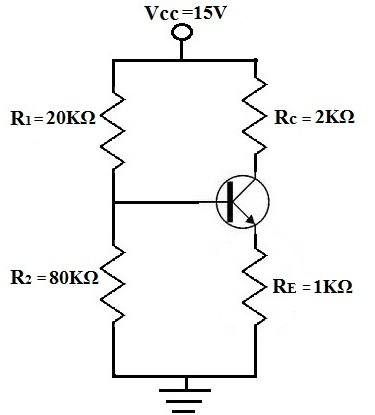
For the circuit above, we're going to assume that β=100 for the transistor.
The base supply voltage, VBB, is calculated by:

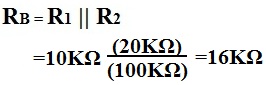
We calculate RB below, which we will use the next calculation for IE.
Then, we calculate for the emitter current using the following formula:
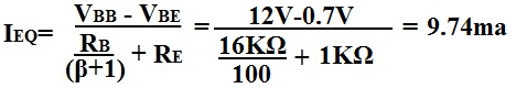
The collector current IC is approximately equal to the emitter current.
IC≈ IE
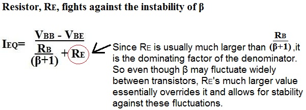
How Emitter Resistor, R
The RE provides stability in gain of the emitter current of a transistor circuit. of a transistor, its gain or amplification factor, can vary by large amounts from transistor to transistor,
even if they're the same exact type from the same batch. There is no way to replicate the same exact βs across
transistors. Therefore, when we are designing transistor circuits where we want roughly the same gain in all of them,
we must design them in a way that produces the same gain despite fluctuations in the β values. We do this by carefully
choosing the emitter resistance, RE, which provides stability against differences in β. RE provides stability
in gain of the output current of a transistor circuit.
For the above transistor, the β was equal to 100. But let's say we have to swamp out that transistor and the new transistor has a β of 150. What will the new calculation be, and will the output current of the transistor swing largely in changes to the β or will it vary little and still be stable?
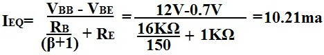
The answer is, the transistor output current doesn't vary much despite the large difference in β values of the transistors. Even though there is a difference of 50 of β in the transistors, there is less than a half of milliampere difference in the output current, IE. If wanted, an even larger value of RE can be used so that there is even more stability against the β of transistors. However, realize that the larger RE is, the more gain that is lost for amplification in the circuit. So there must be balance in the design of the value of RE.
Advantages of the Voltage Divider Bias
Again, voltage divider bias is the most popular and used way to bias BJT transistors. The resistors help to give
complete control over the voltage and current that each region receives in the transistor. And the emitter resistor, RE,
allows for stability of the gain of the transistor, despite fluctations in the β values.
Emitter Bias
Another way to bias a transistor is emitter bias.
Emitter bias is a very good and stable way to bias transistors if both positive and negative power supplies are available. Emitter bias fluctuates very little with temperature variation and transistor replacement.
Below is a BJT transistor receiving emitter bias:
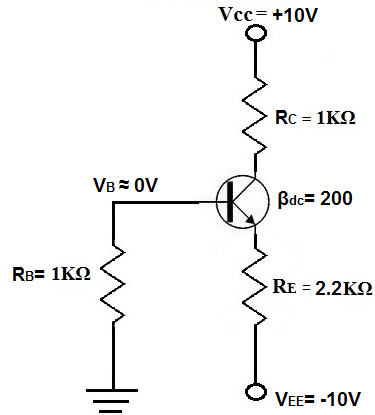
You can see how that both positive and negative voltage supplies are necessary to bias a transistor in this way. Positive voltage is fed to the collector of the transistor and negative voltage is fed to the emitter.
Calculations
Assuming this is a silicon transistor, the voltage drop across the base-emitter diode is equal to 0.7V.
To calculate the emitter current, IE, the formula is:
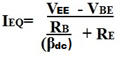
So in the circuit above, the emitter current calculation is:
IE= (10V - 0.7V)/(2.2KΩ + (1KΩ/200))= 4.22mA
To calculate the collector voltage, VC, the formula is:
VC= VCC - ICRC = 10V - (4.23mA x 1KΩ) =5.77V
Again, emitter bias is an effective way to bias a BJT transistor. However, the
voltage divider bias
is still
the most popular way to do so, while
base bias is the least popular way because of the instability it provides if β changes.