
What Clock Frequency Does a USB Module Need in an STM32F446 Board?
In this article, we explain what clock frequency a USB module of an STM32F446 board needs in order to operate properly and we show how to achieve this with the clock system that the board has.
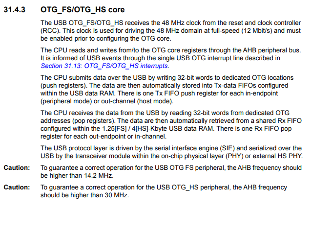
Most USB modules of most STM32 board, including the STM32F446 (a board we use often on this site), require 48MHz in order to function properly.
An important point is that it requires exactly 48MHz, nothing below and nothing above 48MHz. It needs 48MHz. For example, feeding the USB module 38MHz or 52MHz will not allow it to function properly. Anything other than 48MHz will be an improper clock signal.
USB devices are high-speed devices that require relatively high clock speeds.
This allows USB devices to operate with high speed and achieve tasks quickly such as transferring data.
This 48MHz is highlighted in the datasheet and is shown below.
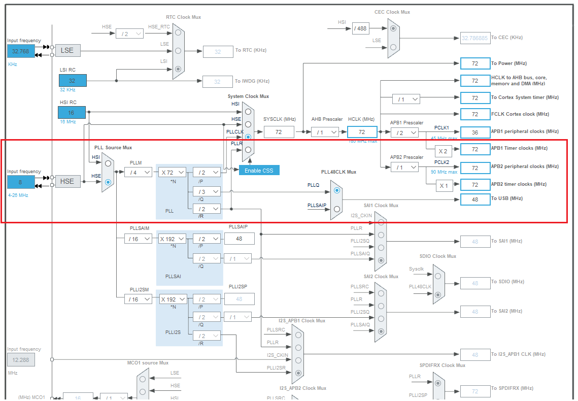
Now that we know that the USB module requires this clock frequency, let's see how we can get this frequency from the clock system of an STM32 board. Specifically, we will look at the STM32F446 clock tree to determine how to get an output clock of frequency of 48MHz.
This is shown in the diagram below.
So let's break this down.
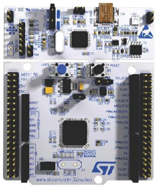
So the best approach to getting the 48MHz clock signal needed for the USB is to get it from the high-speed external (HSE) clock source. This is obtained from the external crystal oscillator, which is 8MHz on the board.
In order to go from 8MHz to 48MHz, we're obviously going to need a multiplier. The PLL is the only way of multiplying a clock signal on an STM32 board.
So we pass this signal through the PLL Source Mux.
There are several ways of getting the output clock frequency of 48MHz.
In our method, we divide the clock by /4 with PLLM, X72 with N, and then divide it by /3 with Q.
Notice that Q is the path to the USB. Look carefully at the diagram.
P leads back to the SYSCLK.
R goes to PLLR, which goes to either SAI1 or SAI2.
So the path we really need is Q, which leads to the clock output that feeds the USB module.
So 48MHz is the clock signal that a USB module needs in an STM32 board in order to function properly
and we need the PLL clock signal in order to achieve this 48MHz signal.
Related Resources