
How to Build a Voltage Doubler Circuit
In this project, we will show how to build a voltage doubler circuit.
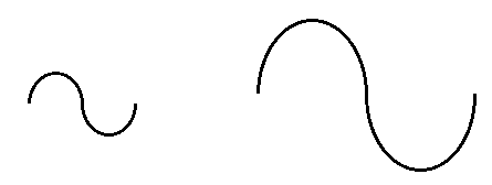
A voltage doubler circuit is a circuit in which the output voltage is double the amplitude of the input voltage.
This voltage doubling effect is achieved through the use of capacitors. We use individuals capacitors to charge up to the input voltage. The first capacitor charges up to the input voltage of the circuit. The second capacitor has a successive effect. It charges up to the value of the input voltage but also sees the voltage from the first capacitor, having an additive effect. The result is double the input voltage. We use diodes to block capacitors from discharging once they are charged. So it's a series of capacitors and diodes that allows this multiplying effect.
The circuit intakes an input voltage and multiplies it by 2 to give an output voltage that is 2 times larger than the input voltage. Thus, this circuit is a type of voltage multiplier circuit.
The circuit intakes an AC voltage signal and outputs a larger DC voltage signal. Thus, the circuit is a type of AC-to-DC converter, an AC-to-DC boost converter.
We'll show exactly below how to connect this circuit and explain in detail how it works.
Components Needed
- 2 1N4001 Diodes
- 2 100μF electrolytic capacitors
So all that is required for this circuit are diodes and capacitors.
Really any diode can be used. It's probably better to use a diode that has a lower voltage drop across the diode than a higher one if you can. In order for a diode to work, it needs sufficient voltage dropped across it. Silicon diodes typically use about 0.7V. Other diodes, such as germanium use less, about 0.3V in order to operate. Therefore, using a lower voltage drop, the output voltage is more accurately double the input voltage. However, it is significant especially if you are using a large input voltage, so we use silicon diodes.
The diodes are used simply for the purpose of routing current where we want it to go during specific phases of the AC voltage cycle. Since the diodes are one-way devices, current can only flow in one direction and are blocked from flowing in the other direction. Using diodes, we can determine which capacitors we want to charge up during the cycles of the AC voltage.
The capacitors we use all all 100μF electrolytic capacitors. Lower values can be used, such as 20-50μF, but these are hard to find, so we simply use 100μF, but you can experiment with this.
The other specification you must take into account with capacitors is the voltage rating. Depending on the input voltage you are using, you must choose the voltage ratings of the capacitors in accordance.
The capacitors should be a little greater than twice the peak of the input voltage, since the voltage will be doubled in this circuit.
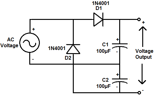
Voltage Doubler Circuit
The voltage doubler circuit that we will build with capacitors and diodes is shown below.
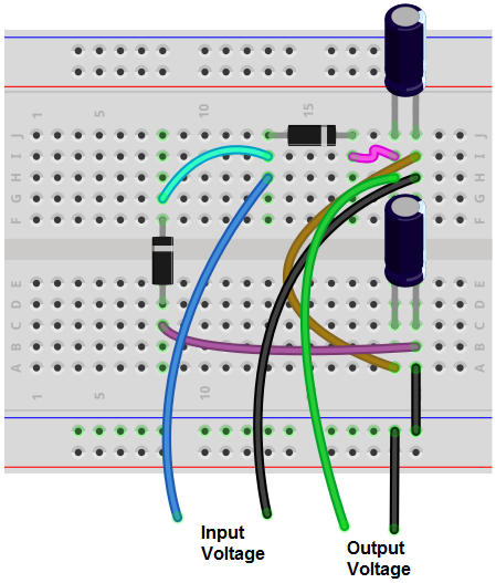
The breadboard circuit of the circuit above is shown below.
So this circuit receives power from an AC voltage source such as a transformer.
Do know that this circuit works off of the basis of AC voltage.
It will not work with DC voltage.
The diodes are positioned in such a way that they are utilized to work with AC voltage.
So just realize that it must be an AC voltage source.
So at the start of the circuit, we have an AC voltage source powering the circuit.
An AC voltage cycle consists of a positive cycle for one-half of the AC voltage and a negative cycle of the other half of the AC voltage.
On the positive half of the AC cycle, current travels from the diode D1 and charges up capacitor C1. When fully charged, C1 equals the same voltage as the input voltage.
On the negative half of the AC cycle, current travels through diode D2 and charges up capacitor C2. Capacitor C2 charges up to the same voltage as the input voltage.
If you did a KVL loop around the 2 capacitors, you see that each of the voltages across the capacitors add up to give the full output voltage. This is how the output voltage is double, or 2 times, the input voltage.
So the output voltage is directly determined by the number of capacitors. In this circuit, we want to double the voltage, so we use 2 capacitors. So if we want triple the input voltage, we would use 3 capacitors. It would require a different circuit configuration but the factor that you would the output voltage to be larger than the input voltage, it requires that amount of capacitors. So if you want the output voltage to be 4 times greater than the input voltage, it would require 4 capacitors.
The diodes in the circuit are configured just so that during each half of the cycle, one is forward biased to allow the capacitor to charge up. During the positive cycle, diode D1 is forward biased, which allows current to flow through it and charge capacitor C1. During the negative half of the cycle, diode D2 is forward biased and allows current to flow thorugh it and charge capacitor C2.
And this is how a voltage doubler circuit can be built with capacitors and diodes.
Related Resources
Voltage Tripler Circuit
Voltage Quadrupler Circuit