How to Build a Voltage Gain Op Amp Circuit
In this project, we will build a voltage gain op amp circuit.
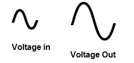
This is a circuit in which we produce voltage gain- the voltage output will be greater by a certain factor than the voltage input.
Basically the circuit is an amplifier.
This has application such as for use with audio signals to create greater volume. This can be used for function generators to amplify signals by a certain factor. Basically, for any type of circuit where amplification is needed, this circuit can be used.
To build our op amp gain circuit, we will use a LM741 chip.
An LM741 is a general purpose amplifier chip.
We will use this op amp in this chip to build a circuit that produces a voltage gain of about 10. This means the voltage output
will be 10 times greater than the voltage input. We can do this easily by putting the correct-valued resistors in place with the chip.
components Needed
- LM741 Op Amp Chip
- 1KΩ resistor
- 10KΩ resistor
- AC Signal Source
The LM741 is a widely used and available chip in the electronics world. It can be obtained from many different online electronics retailers.
It is composed of a single op amp which serves as a general purpose amplifier.
The chip is an 8-pin chip. Its pinout is shown below.
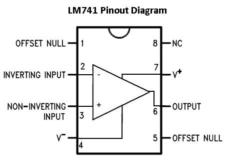
The pins we are going to connect are pins 2, 3, 4, 6, and 7. Pins 1, 5, and 8 will be left unconnected.
For the LM741 to work, it needs power. The LM741 is a dual power supply op amp. This means it needs 2 sources of power. It needs positive voltage at pin 7 and negative voltage at pin 4.
The remaining 3 pins are the 2 inputs and 1 output of the op amp. Of the 2 input pins, one pin is the inverting input and the other is the noninverting input.
To learn in more thorough detail the pinout of the LM741, see LM741 Pinout Connections.
For this circuit, we will input an AC (alternating current) signal into the op amp, which serves as our input signal. This is the signal which will be amplified by the op amp to produce a much larger signal on the output. A great source for AC signals is a function generator. A function generator can generate perfect sine wave signals. These are easy to see on an oscilloscope. So if you have a function generator, you can use a signal from it as the input signal for the circuit.
Also, if you have an oscilloscope, this can be used to visually see and measure the input signal going into the op amp and the much greater amplified signal going out. So that you can measure the gain of the amplifier circuit.
All this is shown below.
Voltage Gain Op Amp Circuit
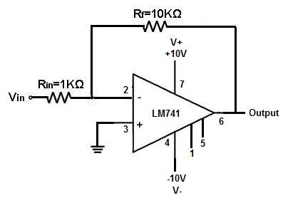
The op amp circuit which produces a voltage gain is shown below.
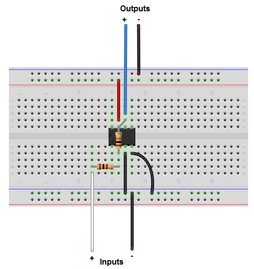
The breadboard schematic version of the above circuit is shown below.
In this circuit, we use the inverting terminal of the op amp as our signal input source. The noninverting terminal is grounded in the circuit. What is meant by inverting terminal is that the signal on the output will be flipped or out of phase by 180 degrees. You don't really have to worry about this too much.
This circuit above provides a gain of about 10. This means the voltage output will be 10 times greater than the voltage input. So the gain factor is 10.
This gain factor is obtained from the resistors used in the circuit. We have 2 resistors, RIN and Rf. The ratio of Rf/RIN determines the gain. Since 10KΩ/1KΩ is 10, our op amp circuit gives a gain of 10.
If we wanted a gain of 5, then we could swap out the 10KΩ resistor and place a 5KΩ resistor. If we want a gain of 15, we could swap out the 10KΩ resistor with a 15KΩ resistor.
Remember to watch your limits. You can't have a gain that's too high like 100,000, unless you have a really low input signal. Because then the signal on the output will clip.
When you place DC voltage into the V+ and V- terminals, you are setting up rails that the output signal must be boxed in, or else it will clip at point near the peak of the signal. By placing +10V and -10V into the supply voltage terminals, we set up rails so that the output signal must be between +10V and -10V. If it is larger, it will clip. Therefore, when designing your circuit, calculate your input signal and the gain provided so that the amplified output signal is not greater than the rails established by the power supply.
In this circuit, we put it in +10V and -10V into the supply voltage terminals. Knowing this and with a gain of 10, we can have a maximum input signal of 1V. This is because 1V * 10 = 10V, right where our positive and negative rail will be. But it should really be a little under 1V. Because you don't want the output signal to be right at the point of saturation because then you run the risk of it clipping. In case like this, the input signal should be kept a little lower or the voltage going into the power supply terminals should be a little higher.
To test this circuit out, place a sine wave signal at the inverting terminal of the op amp. Use an oscilloscope to test out
the signals. If you have a 2-channel oscilloscope, you can use one channel on the input side to check the input signal and one channel on the
output side to check the output signal. You should then be able to easily see and measure the difference in the signals. The gain should show
about 10 times the value on the output signal.
Related Resources
How to Build a Non-inverting Op Amp Circuit