
How to Build a Voltmeter Circuit with Zener Diodes
In this circuit, we will show how to build a voltmeter using zener diodes.
A voltmeter is a device that can measure voltage and give out a status indicator of what the voltage level is.
The voltmeter we build won't be capable of showing the voltage output on a digital screen such as an LCD. It shows us the voltage strength by the number of LEDs that are lit.
We place multiple zener diodes in parallel in a circuit. Each zener diode has a different breakdown voltage. As we go from left to right, each successive zener diode has a greater breakdown voltage. So as the voltage rises, the number of LEDs that turn on increase. This is because as the voltage gets greater, more zener diodes surpass their breakdown voltage and conduct current across from cathode to anode to light up the LEDs.
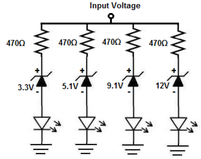
In this circuit, we use 4 zener diodes. These diodes have breakdown voltages of 3.3V, 5.1V, 9.1V, and 12V.
So if the voltage rises above 3.3V, one LED will light up.
If the voltage rises above 5.1V, 2 LEDs light up.
If the voltage rises above 9.1V, 3 LEDs light up.
And if the voltage rises above 12V, all 4 LEDs turn on.
So the number of LEDs that are lit serve as a visual status indicator of the voltage level.
Components Needed
- 1N4739 9.1V Zener Diode
- 1N4733 5.1V Zener Diode
- 1N4741 12V Zener Diode
- 1N4728 3.3V Zener Diode
- 4 470Ω resistors
- 4 LEDs
The 1N47XX zener diodes can be obtained very cheaply from a number of online retailers. They can be obtained from Tayda Electronics at the following link: 1N47XX Zener Diodes.
The datasheet for these diodes can be found at: 1N47XX Zener Diode Datasheet.
This diode again have breakdown voltages of 3.3V, 5.1V, 9.1V, and 12V, for the 1N4728, 1N4733, 1N4739, and 1N4741. After a breakdown voltage is reached, the diode will break down and conduct current across from cathode to anode.
The pinout for a zener diode is shown below:
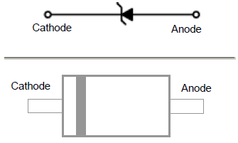
The cathode end of the zener diode is the end with the band on it. The other end is the cathode.
All the zener diodes will be connected reverse biased to the power supply.
Voltmeter Circuit with Zener Diodes
The voltmeter circuit we will build with zener diodes is shown below.
The breadboard schematic of the above circuit is shown below.
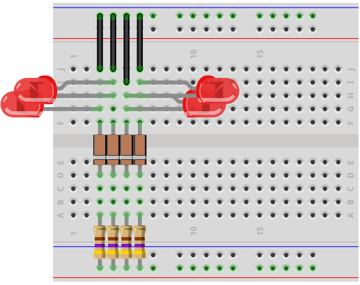
So the circuit is very simple.
The zener diodes are all connected in reverse biased to the power source. Each zener diode has a 470Ω resistor in series with it to limit current to the LED and then we have the LED.
How this circuit works is the power source feeds voltage to the circuit.
When the voltage goes above the 3.3V threshold, then the zener diode breaks down and begins to conduct current across from its cathode to its anode. This current then powers on the LED, lighting it up. So if the voltage is above 3.3V but below 5.1V, the first LED will turn on.
When the voltage goes above the 5.1V threshold, then the first 2 LEDs are lit, since both diodes' breakdown voltages have been reached.
When the voltage goes above the 9.1V threshold, then the first 3 LEDs are lit, since the 3 diodes' breakdown voltages have been reached.
When the voltage goes above the 12V threshold, then all 4 LEDs are lit, since all 4
So if none are on, this means the input voltage is less than 3.3V.
If only 1 is on, this means the input voltage is between 3.3V and 5.1V.
If 2 are on, this means the input voltage is between 5.1V and 9.1V.
If 3 are on, this means the input voltage is between 9.1V and 12V.
If 4 are on, this means the input voltage is greater than 12V.
So this is how the LEDs serve as status indicators of the voltage levels.
You can make many modifications to this circuit. You can swap out this zener diode for another to get different voltage thresholds.
The types of zener diodes you can use with their breakdown voltages are:
1N4729: 3.6V
1N4730: 3.9V
1N4731: 4.3V
1N4732: 4.7V
1N4734: 5.6V
1N4735: 6.2V
1N4736: 6.8V
1N4737: 7.5V
1N4738: 8.2V
1N4740: 10V
1N4741: 11V
1N4743: 13V
1N4746: 18V
These are many different zener diodes you can use. They all have different breakdown voltages, so they can set a different threshold voltage for the voltage level indicator circuit.
And this is how a volmeter can be built with zener diodes.
To see how this circuit works in real life, see the following video
shown below.
Related Resources
How to Build a Zener Diode Voltage Regulator
How to Build a Voltage Level Indicator with a Zener Diode