What are Unijunction Transistors?
Unijunction transistors are three-lead transistors that act exclusively as electrically controlled switches; they are not used as amplifiers.
This differs from other transistors in that general transistors usually provide the ability to act as a switch and also as a an amplifier. But a unijunction transistor does not provide any decent type of amplification because of the way it is constructed. It's simply not designed to provide a sufficient voltage or current boost.
The basic operation of a UJT is relatively simple. When no potential difference (voltage) exists between its emitter
and either of its base leads (B1 or B2), only a very small current flows from B2 to B1. However, if a sufficiently large positive trigger
voltage- relative to its base leads- is applied to the emitter, a larger current flows from the emitter and combines with the small B2-to-B1
current, thus giving rise to large B1 output current. Unlike other transistors- where the control leads provide little additional
current- the UJT is just the opposite. Its emitter current is the primary source of current
for the transistor.
The B2 to B1 current is only a very small amount of the total combined current. This means that unijunction transistors are not suitable
for amplification purposes, but only for switching.
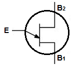
This diagram above shows how the transistor operates. Once the emitter receives sufficient voltage, a larger current flows from
B2 to B1.
Unijunction Characteristics
Unijunction Transistor Charactertistics Curve
This unijunction transistor characteristics curve helps explain how a unijunction transistor behaves when differing levels of voltages are fed to it.
This helps explains the characteristics of a UJT, since we monitor its behavior when different voltage levels are given to it, which in turn, helps us understand
UJTs better.
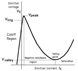
At first, when insufficient voltage is given to the transistor, it does not turn on. Then as the voltage is increases and hits the transistor's triggering voltage, which is its threshold voltage, and it turns on. The transistor then passes through a negative resistance region, which sees an increase in current and a drop in voltage. It then goes to the saturation region, where the current and voltage of the transistor increases.
Explanation of Characteristics Curve
We'll now explain what each region means means so that you can better understand it.
Cutoff- This is the region where the unijunction transistor doesn't yet receive enough voltage to turn on.
The voltage han't yet reached the triggering voltage, so the transistor will not turn on.
Negative Resistance Region- After the transistor has reached the triggering voltage, VTRIG, it now will turn on. After
a while if the applied voltage still increases to the emitter lead, it will peak out at VPEAK. From VPEAK to the Valley Point, the applied
voltage drops while the current, though, increases. The current increases but the voltage decreases, which is
why it's called negative resistance.
Saturation- After the negative resistance region which saw an increase in current comes the saturation region.
This is the region
where if the applied voltage to the emitter still increases, the current and voltage will rise.