
When to Use Internal or External Pull-up or Pull-down Resistors in an STM32 Board

In this article, we explain when to use internal or external pull-up or pull-down resistors in a circuit using an STM32 board.
Whether you should use an internal or external resistor depends on the type of circuit you are building, and there are a few things to consider whether you choose to use an internal resistor or an external resistor.
Some people may think you should always go with internal pull-up or pull-down resistors because then you don't have to add one physically to your circuit. Though it is true that it does save you from adding extra components to a circuit, this cannot always be the case.
One of the problems with this is that the internal pull-up or pull-down resistors are of a fixed value. The value cannot be modified.
Below is a table of the I/O port characteristics of an STM32F407 board that shows the
pull-up and pull-down resistor values.
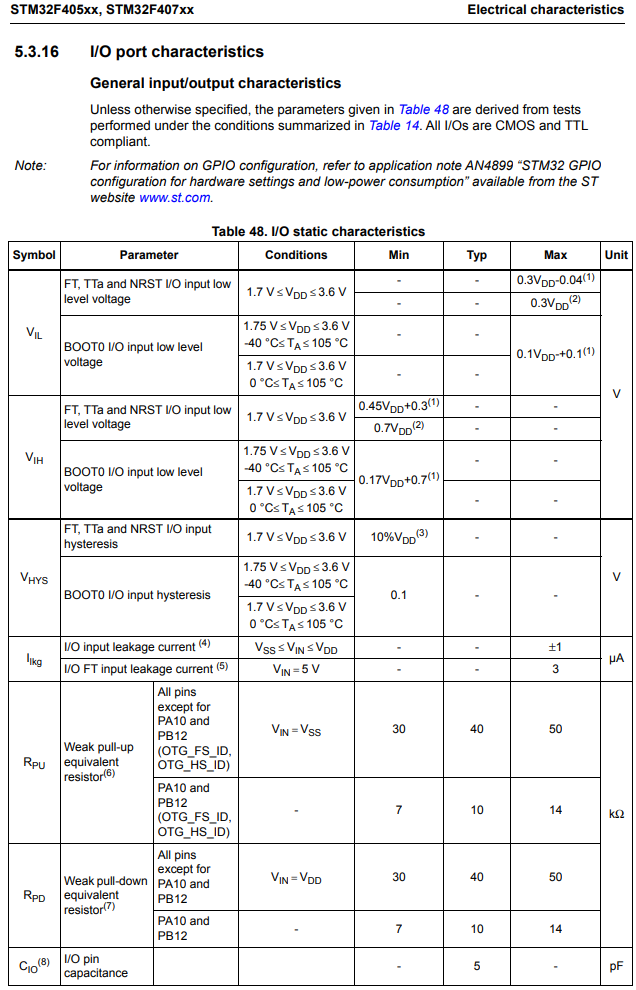
You can see that with the exception of GPIO port pins PA10 and PA12, which have pull-up and pull-down resistors of 10KΩ, all of the other port pins have resistance values of 40KΩ.
If you are just pulling up or pulling down a I/O port to define its state, then you can use internal resistors and the value of the resistor doesn't really matter.
However, there may be times when you need to use the pull-up resistor to drive a device such as an LED.
In this case, you couldn't use a 10KΩ or a 40KΩ resistor, because the current would be too small to drive the LED.
In a case such as this, you would have to use an external resistor such as a 1KΩ or a even a lower value depending on the type of LED you are working with.
Again, you cannot modify any of the internal pull-up or pull-down resistors.
If none of these values work for the circuit you are building, because, for example, the current would be too low or too high, then you will have to use an external pull-up resistor.
For example, let's say we have a GPIO port pin with an LED connected to output and we are using the open-drain output configuration.
The open-drain output configuration requires a pull-up resistor in order to have a load in the HIGH logic state (or ON).
This is shown in the diagram below.
You couldn't use the internal pull-up resistor of STM32, because the current would be too small to power the LED with such a high resistance value.
Instead you would have to disable the pull-up and pull-down resistors (which occurs by default) and add an external resistor such as 220Ω to power the LED.
Other times, using an external pull-up or pull-down resistor is beneficial if you simply want the state of a pin defined and you are not powering any current-sensitive device.
For example, we may need to configure GPIO port pins as input pins if we are reading from them. For example, let's say we add a simple SPST push button switch to an I/O pin. Because we need to read from the logic state of this switch, we set the I/O pin as input.
For the setup of this switch, we connect one end to ground and the other end we connect to the I/O port.
When the switch is pressed down, it has direct electrical connection with ground, so it will always read a 0 or LOW logic state.
However, when the switch is open, it has no direct connection to either GND or VDD (a logic HIGH); therefore, it is in a floating state and noise can make it randomly HIGH or LOW. This would be horrible for our circuit, because it would give false readings.
In order to prevent this, we pull the switch up to a HIGH voltage state. Thus, when it is open, we read a 1 or logic HIGH. And when it is pressed, we read a 0 or logic LOW.
In this case, the value of the pull-up resistor does not matter because we simply want to define the logic state of the pin and are not worried about current.
In this case, it is beneficial to use an internal pull-up resistor, as it requires our circuit to have less external components and is an efficient use of a pull-up resistor.
So the STM32 microcontroller has a GPIO port pull-up and pull-down register, which is shown below.
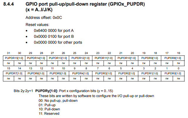
By default, a GPIO port pin is configured as an input. So no changes are needed there.
So if you want to add a pull-up resistor to the GPIO port pin, then you set that pin to 01 (pull-up mode).
This add the internal pull-up resistor to that pin and now with the switch we have 2 well defined states for
when the switch is open (HIGH) and when the switch is closed (LOW).
So examples such as these help illustrate when to use an internal or external pull-up or pull-down resistor
when building a circuit using an STM32 microcontroller board.
Related Resources