
How to Build a Vibration Detector Circuit

In this project, we will go over how to build a vibration detector circuit.
This is a circuit which can detect and measure flex, touch, vibration, and shock.
The sensor we will use to detect these movements is a piezo vibration sensor from Measuremenet Specialists (MEAS).
The sensors are a thin strip of piezoelectric material with a rivet in the end acting as a weight. When there is a vibration, the weight moves, stressing the piezo material that produces a spike in voltage. This voltage that is created may be up to 90V.
We are going to connect this vibration sensor to an arduino which can read and detect these voltages that the sensor creates when there is vibration. With the resistance which an analog terminal of an arduino offers, these voltages of up to 90V will be brought to safe levels that will not harm the arduino board. When the arduino detects vibration, the LED connected to it will light up for a second and then turn off with each vibration above a certain threshold value.
This circuit is used often for impact sensing or as a flexible switch. If
the piezo sensor is flexed, a large voltage will be created which can switch on a transistor,
SCR, or any other type of switching device.
Components Needed
- Arduino Board
- Piezo Vibration Sensor
- LED
The piezo vibration sensor is from the company MEAS. It can be obtained from a number of online retailers for a very low price (under $5). Follow this link to the piezo sensor offered by Sparkfun- Sparkfun- Piezo vibration sensor.
The piezo sensor is a 2-pin device. One pin represents the positive terminal, while the other pin represents the negative or ground terminal.
Below is the pinout of the sensor:

We will connect the 2 pins to analog terminal A0 and A1 of the arduino board.
We will then in our code set one to LOW, representing ground, while the other pin will
be the sense pin, which will sense for any vibrations that are made in the sensor's vicinity.
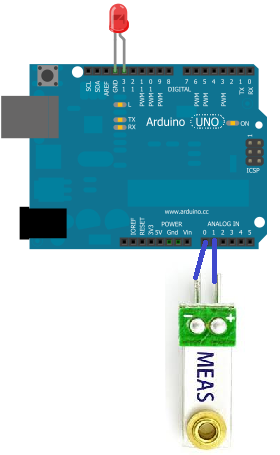
Vibration Detector Circuit
Below is the circuit of the vibration detector:
Below is the schematic diagram of the above circuit:
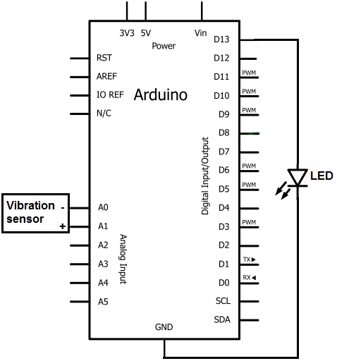
The piezo sensor works very well with the arduino. It 2 pins simply go into analog terminal A0 and A1 of the arduino. A0 will be configured to be ground and A1 will be the positive sense pin of the vibration sensor. This pin will detect whether there is any vibration or not.
The LED's positive pin (the anode) will go into digital pin 13 of the arduino and the negative or ground lead (the cathode) will be connected to ground. No resistor needs to be connected in series with the LED because digital pin 13 has built-in resistance. Therefore, there is enough resistance intrinsically to limit current going to the LED, such that no external resistor is necessary.
With this hardware setup, we will program the software so that this LED lights up when vibration above a certain threshold is reached.
Now that we have our circuit setup, we now just need to connect the arduino to a computer via a USB. The type A connector goes into the computer and the type B goes into the arduino.
Once this is in place, we can now write the code to program the circuit.
Code for Vibration Detector Circuit
int GroundPin= 0;
int sensePin= 1;
int LEDPin= 13;
int threshold= 500;
void setup()
{
Serial.begin(9600);
pinMode(GroundPin, OUTPUT);
digitalWrite(GroundPin, LOW);
pinMode(LEDPin, OUTPUT);
}
void loop()
{
int reading= analogRead(sensePin);
Serial.println(reading);
if (reading > threshold)
{
digitalWrite(LEDPin, HIGH);
delay(1000);
digitalWrite(LEDPin, LOW);
}
}
The first block of code defines the pin connections. The ground pin (of the sensor) will be put in A0 of the arduino. The sensepin will be placed in A1. And the LEDPin will be placed in digital pin D13.
The second block of code defines a variable called threshold. This is a very important variable because it represents the analog level at which the LED will be triggered to turn on. The arduino can detect and measure analog values from 0 to 1023. We created it so that once an analog sound vibration reaches 500 or greater, the LED will be triggered on. You can modify this value to be less or greater depending on the amplitude of the vibration you want to be the trigger point. However, a value near 500 is good for all practical purposes. If you lower the threshold value, then the circuit will detect vibrations easier. If you raise the threshold value, the circuit will need greater vibrations in order to trigger.
The third block of code sets up the A0 terminal as the ground pin. It must be set as output and then declared LOW in order to function as a ground. This serves as the ground for the negative lead of the piezo sensor. The LEDPin serves as a digital output pin for the LED we connect to D13, so it must be declared output. We put the line Serial.begin(9600) so that if we want, you can see the values that the arduino is reading from the sensor if you had the line Serial.println(reading), for testing purposes.
The fourth block of code is the loop() function. The reading variable
measures the actual voltage on the sensePin of the vibration sensor, which is the positive
terminal connected to A1. If the reading is larger than the threshold value,
the LED will be triggered to high and turned on. If not, it does not turn on. With this code,
we only turn the LED on when the vibration is a large enough amount. If you want, you can
set the threshold to a higher amount, so that the LED only turns on for a greater impact
force to the sensor. Play around with this to suit your needs.
And this is how a vibration sensor works integrated with an arduino board. With this circuit, the LED will turn on for a second with each vibration above the given threshold and then turn off.
Again, several variations of this circuit can be done to fit your needs. Maybe you don't want an LED to light when vibration is detector. Maybe you want a buzzer to sound. In that case, you replace the LED with a buzzer. Maybe you don't want a buzzer. You want a fan to go off. There are many ways the circuit can operate. Customize according to your needs.
To find out how to build an alarm circuit that goes off when it detects vibration, visit how to build a vibration alarm circuit.
Below is the real-life circuit built so that you can see how it works.
Related Resources
How to Build a Vibration Motor Circuit
How to Build a Hall Effect Sensor Circuit
How to Build a Touch Sensor Circuit
How to Build an Accelerometer Circuit
How to Build a Motion Detector Circuit
How to Build a Motion Detector Alarm Circuit
How to Build a Piezo Knock Sensor Circuit