
How to Connect a 24LC256 EEPROM to an Arduino
In this project, we will show how to connect an 24LC256 EEPROM chip to an arduino micrcontroller.
EEPROM stands for Electrically Erasable Programmanble Read-Only Memory.
EEPROM is very important and useful because it is a non-volatile form of memory. This means that even when the board is powered off, the EEPROM chip still retains the program that was written to it. So when you power off the board and then power it back on, the program that was written to the EEPROM can be run. So basically, the EEPROM stores and runs a program no matter what. This means you can turn off a device, keep it off for 3 days, and come back and turn it on and it can still run the program that was programmed in it. This is how most consumer electronic devices work.
EEPROM is also very efficient in that individual bytes in a traditional EEPROM can be independently read, erased, and rewritten. In most other kinds of non-volatile memory, this can't be done.
In this circuit, we will show how to connect a 24LC256 to an arduino and how to program the arduino
so that it can write to and read from the 24LC256 chip. We can write anything that we want to it (as long as it's within
256 kilobits of memory) and read from it any time we want.
Components
- 24LC256 EEPROM chip
- 10KΩ resistor
- Arduino microcontroller
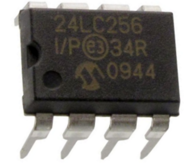
The 24LC256 EEPROM chip can be obtained for a little over $1 on ebay.
The 24LC256, as the last 3 digits imply, gives an additional 256 kilobits of EEPROM to an arduino micrcontroller. The EEPROM available on an arduino uno is 512 bytes of memory. So adding 24LC256 chip for EEPROM expansion is a significant one. It gives great EEPROM expansion.
The 24LC256 EEPROM can operate on power anywhere from 2.5-5.5V.
The datasheet for the 24LC can be found at the following link: 24LC256 EEPROM Datasheet.
The 24LC256 is an 8-pin chip. The pinout of this chip is shown below.
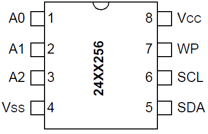
First, to power the chip, we connect VCC, pin 8, to 5V. And we connect GND, pin 4, to power ground.
The address input pins, A0, A1, and A2, are for multiple device operation. If you are going to connect more than one 24xx256 EEPROM to a microcontroller, you will need to vary the addresses of each of the pins. So there are 3 address, which means there can be a total of 8 EEPROM devices connected together to a microcontroller (since 23= 8). If you have 8 EEPROMs connected together, each of them must have a unique address. The possible addresses are 000, 001, 010, 011, 100, 101, 110, and 111. The reason why each EEPROM must have a unique address is because there would be no other way for the microcontroller to address a specific one. The address is how you can differentiate between all the EEPROM chips. In this circuit, we simply connecting one EEPROM device to the microcontroller. Even with only being used, an address still must be used. We will ground all the address pins. This produces an address of 000. So this is what we will use for this circuit. But you can really make the address anything based on what address pins you pull HIGH or LOW. If you make A0 HIGH and A1 and A2 LOW, then this is an address of 001. If you make A1 and A2 HIGH and A2 LOW, then this is an address of 011. If you make all 3 address pins HIGH, this is an address of 111. It really doesn't matter when you have a single EEPROM. Just remember that when you connecting multiple devices, each one must be unique.
The WP pin, pin 7, is the Write-Protect pin. This pin can enable or disable the microcontroller writing data to the EEPROM chip depending on whether the pin is pulled HIGH Or LOW. If tied to HIGH or VCC, write operations are inhibited. Read operations, however, are not affected. If tied LOW or to VSS, write operations are enabled.
The SCL pin, pin 6, is the serial clock line. The 24LC256 operates off a clock signal. The clock is used to synchronize data transfer to and from the device between the arduino microcontroller and the EEPROM chip.
The SDA pin, pin 5, is the serial data pin. This is the pin that transfers data between the micrcontroller
and the EEPROM chip. It's bidirectional.
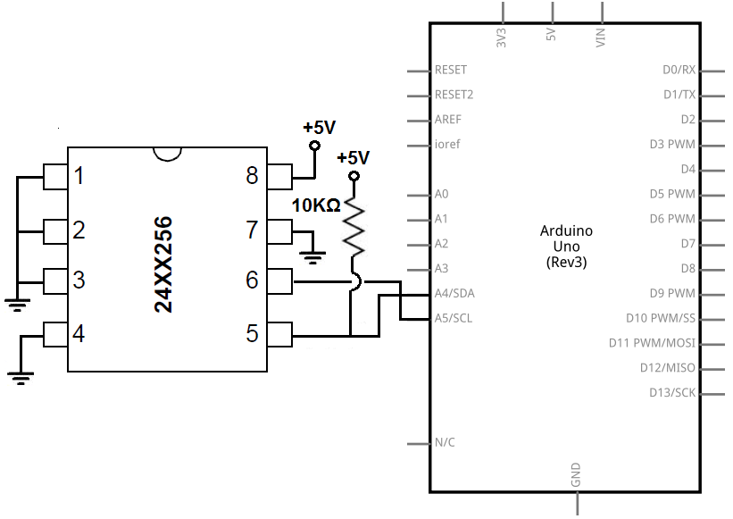
24LC256 EEPROM Circuit with an Arduino
The circuit of the 24LC256 EEPROM we will connect to an arduino microcontroller is shown below.
The breadboard circuit of the circuit above is shown below.
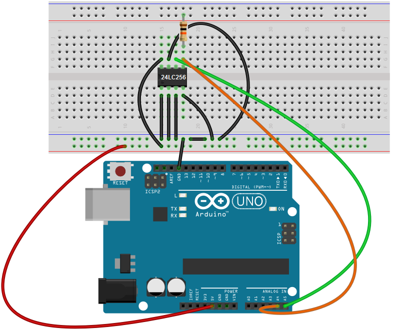
We will now explain the hardware connections.
First to connect power to the 24LC256 chip, we connect VCC, pin 8, to the 5V of power and connect VSS, pin 4, to ground. This establishes power to the EEPROM chip.
The address pins, A0, A1, and A2, which are pins 1, 2, and 3 are all connected to ground. Since they are all grounded, they are all in LOW states. Therefore, the address pins will have a value of 000.
The SDA pin, pin 5, of the EEPROM connects to analog pin 4 on the arduino, which is the SDA terminal of the arduino. This is connected via a 10KΩ pull-up resistor.
The SCL pin, pin 6, of the EEPROM connects to analog pin 5 on the arduino, which is the SCL terminal of the arduino. This establishes a clock line so that the master and slave device can work in synchrony.
The last pin, the WP (or Write Protect) pin connects to ground. Since we want to write to a device in this circuit, we just permanently connect it to ground. In this circuit, we're not interested in disabling the write feature. However, there are times where it may be very necessary. For example, if you've permanently already written your program to EEPROM and you don't want any modifications at all, just the ability to read from the EEPROM, you can disconnect the write feature by permanently tying the WP pin to VCC. Or you can connect it to a digital pin of a micrcontroller, so that you can switch between enabling or disabling it.
These are the hardware connections. Now all we need is the code.
Code
The code to write and read data from from a 24LC256 EEPROM is shown below.
#include <Wire.h>
#define eeprom 0x50
void setup(void){
Wire.begin();
Serial.begin(9600);
unsigned int address = 0;
Serial.println("We write the zip code 22222, a zip code in Arlington, Virginia!");
for(address = 0; address< 5; address++)
writeEEPROM(eeprom, address, '2'); // Writes 22222 to the EEPROM
for(address = 0; address< 5; address++) {
Serial.print(readEEPROM(eeprom, address), HEX);
}
}
void loop(){
}
void writeEEPROM(int deviceaddress, unsigned int eeaddress, byte data ) {
Wire.beginTransmission(deviceaddress);
Wire.write((int)(eeaddress >> 8));
Wire.write((int)(eeaddress & 0xFF));
Wire.write(data);
Wire.endTransmission();
}
byte readEEPROM(int deviceaddress, unsigned int eeaddress ) {
byte rdata = 0xFF;
Wire.beginTransmission(deviceaddress);
Wire.write((int)(eeaddress >> 8));
Wire.write((int)(eeaddress & 0xFF));
Wire.endTransmission();
Wire.requestFrom(deviceaddress,1);
if (Wire.available())
rdata = Wire.read();
return rdata;
}
For an I2C device, which is what the 24LC256 EEPROM is, we import the Wire library. This facilitates I2C communication.
We then define the address of the EEPROM device. The 24LC256 EEPROM has a base address of 0x50. The complete address is 0x50 + A2 A1 A0 value. Since the address pins, in our case, is 000, the final address remains 0x50. However, if the address pins were 111, it would be 0x57. If it was 001, it would be 0x51.
Next, we have our setup() function. Since this is I2C communication, we have to create a Wire object. We then create a serial monitor so that we can see our Serial.println output statements. We then create a for loop where we write out 5 '2's representing a zip code. We then call a for loop reading this value.
We then have a for loop, but it contains nothing because a for loop repeats itself over and over again. With EEPROMs, we don't want that. We want the microcontroller writing to an EEPROM once, not repetitively. Therefore, we put all the functions in the setup() function and not in the loop() function.
Our next 2 blocks of code define the WriteEEPROM function and the readEEPROM function.
And this how we can write and read data to and from an 24LC256 EEPROM with an arduino microcontroller.
Related Resources
How to Build a 74HC238 3-to-8 Decoder Circuit with Manual Pushbuttons