
How to Control a 4-digit 7-segment LED Display with an Arduino
In this circuit, we will show how to display numerals on a 4-digit 7-segment display just by directing using any arduino microcontroller with no other external chips such as LED display drivers.
Simply by using transistors to each of the digits of an LED display, we can have sufficient current going to each digit of the LED display to drive them.
In this circuit, we're going to connect an analog sensor to the arduino microcontroller, simply a potentiometer because it's very easy to deal with. The value of the potentiometer will be shown on the 4-digit 7-segment display, depending of course on the resistance it is offering.
Since we are using a 4-digit LED display, the values can vary from 0 to 9999, 0 being the lowest value and 9999 being the highest. When the potentiometer is offering 0Ω of resistance, the value is 0. As the resistance that the potentiometer offers increases, the value steadily increases. When the potentiometer offers its full, maximum resistance, the value is 9999 (or close to it).
So this is a very good circuit for showing how an arduino can directly control a 4-digit 7-Segment LED
display simply with only using transistors and resistors as additional components.
Components Needed
- Arduino Microcontroller
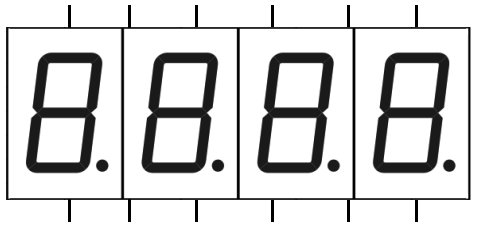
- 4-digit 7-segment LED display
- 4 1KΩ resistors
- 4 2N3904 NPN transistors
- Potentiometer
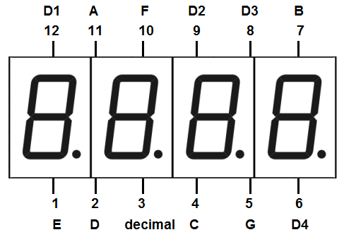
A 4-digit 7-segment LED display has 12 pins. 8 of the pins are for the 8 LEDs on each of the 7 segment displays, which includes A-G and DP (decimal point). The other 4 pins represent each of the 4 digits from D1-D4.
The pinout for the LED segment is shown below.
The potentiometer that is used can be of any value. It doesn't matter.
The transistor we use is a 2N3904 transistor. But really any NPN bipolar junction transistor such as the 2N2222 transistor also.
4-Digit 7-Segment LED Display Circuit with an Arduino
The 4-Digit 7-Segment LED circuit that we will build with an arduino microcontroller is shown
below.
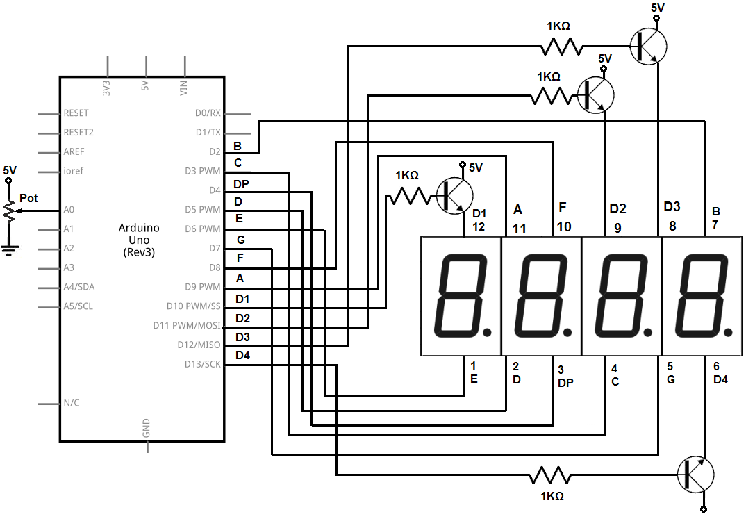
The segment A on the 4-digit 7-segment display connects to digital pin 9 on the arduino.
The segment B on the LED display connects to digital pin 2 on the arduino.
The segment C on the LED display connects to digital pin 3 on the arduino.
The segment D on the LED display connects to digital pin 5 on the arduino.
The segment E on the LED display connects to digital pin 6 on the arduino.
The segment F on the LED display connects to digital pin 8 on the arduino.
The segment G on the LED display connects to digital pin 7 on the arduino.
The decimal point (DP) segment on the LED display connects to digital pin 4 on the arduino.
Digit 1 on the LED display connects to digital pin 10 on the arduino.
Digit 2 on the LED display connects to digital pin 11 on the arduino.
Digit 3 on the LED display connects to digital pin 12 on the arduino.
Digit 4 on the LED display connects to digital pin 13 on the arduino.
To each of the Digits- Digit 1, Digit 2, Digit 3, Digit 4- we connect a transistor with a 1KΩ resistor at each of the bases of the transistors. The transistor gives current amplification, so that there is enough current to drive all the digits of each of the 4 digits of the 7 segment LED displays. Without the transistors, there simply would not be enough current to light up all 4 7 segment LED displays.
As a sensor device, we connect a potentiometer to the arduino. To connect the potentiometer, we connect
the end terminals to power. One end gets connect to +5V and the other end gets connected to ground. The middle terminal,
the wiper terminal, gets connected to analog pin 0 (A0). This way, the wiper terminal can vary in voltage from 0V to 5V.
This voltage in turn will translate into a number between 0 and 9999, through our code below.
Code
The code shows the analog value of a sensor connected to the arduino board.
The value displayed can range anywhere from 0 to 9999 on a four-digit display.
const int sensorPin= 0;
const int numeral[10]= {
B11111100,
B01100000,
B11011010,
B11110010,
B01100110,
B10110110,
B00111110,
B11100000,
B11111110,
B11100110,
};
const int segmentPins[]= { 4, 7, 8, 6, 5, 3, 2, 9};
const int numberofDigits=4;
const int digitPins[numberofDigits] = { 10,11,12, 13};
void setup()
{
for (int i=0; i < 8; i++)
pinMode(segmentPins[i], OUTPUT);
for (int i=0; i < numberofDigits; i++)
pinMode(digitPins[i], OUTPUT);
}
void loop()
{
int value= analogRead(sensorPin);
showNumber(value);
}
void showNumber (int number)
{
if (number == 0)
showDigit (0, numberofDigits-1);
else
{
for (int digit= numberofDigits-1; digit >=0; digit--)
{
if (number > 0)
{
showDigit(number % 10, digit);
number= number/10;
}
}
}
}
void showDigit (int number, int digit)
{
digitalWrite(digitPins[digit], HIGH);
for (int segment= 1; segment < 8; segment++)
{
boolean isBitSet= bitRead(numeral[number], segment);
isBitSet= ! isBitSet; //remove this line if common cathode display
digitalWrite(segmentPins[segment], isBitSet);
}
delay(5);
digitalWrite(digitPins[digit], LOW);
}
This code will display a number between 0 and 9999 based on the value read from the potentiometer.
The first line declares the sensorPin and initializes it to 0 because the sensor, which is the potentiometer, will be connected to analog pin 0.
The next block of code defines all the numeral values. A 7 segment LED display is made up of 8 segments. Being made up of 8 LED segments, in order to show a number on the LED display, we have to enter in which LEDs turn on in the display to show that number. All the values in this block represent the numerals based on the lit LEDs.
The next line defines the array, segmentPins[]. This array defines the pin connections for the segments of the LED display. This defines the pin connections dp, G, F, E, D, C, B, A.
The next line declares the variable, numberofDigits, as 4, since there are 4 digits in the LED display.
The next line is another array that defines digitPins[]. This array defines the pin connections for the digit pins, D1, D2, D3, and D4.
In the setup() function, the first for loop defines the segmentPins all as outputs. It goes through each of the 8 segment pins and declares each one as an output.
The second for loop, similarly, defines all the digit pins as outputs. It goes through each of the 4 digit pins and declares each one as an output.
The next block if the loop() function. In this function, we read the value from analog pin 0 which is the value read from the wiper terminal of the potentiometer; we store this number in the value variable. We then display this number on the LED display with the showNumber() function with the value variable as the parameter.
The next 2 blocks of code define the showNumber() and showDigit() define the 2 functions needed to show the value that the potentiometer reads on the LED display. We won't go
into them now but they're needed in order to actually display the value on the LED display.
And this is all that is necessary to control a 4 digit 7 segment LED display.
Related Resources
How to Vary the Brightness of an LED
How to Build an LED Driver Circuit
How to Build an LED Flasher Circuit