How to Build an LED Flasher Circuit with a 555 Timer Chip

In this project, we will show how to build a simple LED flasher circuit using a 555 timer chip.
An LED flasher circuit is a circuit which flashes the LED- meaning turns it ON-OFF, ON-OFF, ON-OFF.
The 555 timer chip is a very versatile IC, because when connected correctly, it can it can create pulses of current at specific time intervals decided by the resistor-capacitor (RC) network. When a 555 timer creates pulses in this way, the LED doesn't stay constantly on. It only turns on at a pulse and then shuts off after the pulse has passed. And it does this in a never-ending cycle, which creates the flashes of light.
To make the 555 timer chip create pulses, it must be placed in astable mode. Astable mode simply means that the 555 timer has no stable state. It switches constantly between high and low, or on and off. This is why this mode is also called oscillator mode, because it uses the 555 timer an oscillator, which creates square wave signals.
To create an LED flasher circuit, the parts which we need to do so are:
Components Needed
- 555 timer IC
- 9-volt Battery or DC power supply
- Red LED
- 2 1KΩ Resistors
- 10KΩ Resistor
- 10µF electrolytic capacitor
- 0.01µF ceramic capacitor
- Several jumper wires
For this circuit, you can use a 9-volt battery as the power source or if you have a DC power supply, you can just adjust so that it gives out 9 volts.
For this circuit, you will need several jumper wires because to connect all the resistors and capacitors to the 555 timer chip
does become complicated. To simply the breadboarding of this circuit, jumper wires help to space out the circuit so that everything isn't jumbled
on top of each other.
LED Flasher Circuit
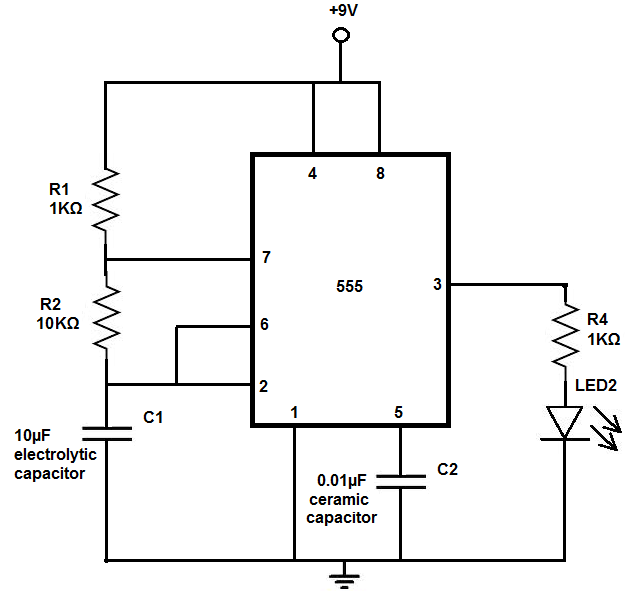
The schematic diagram of the LED flasher circuit we will build is shown below:

This circuit will flash the LED on and off, on and off.
The rate that the LED flashes is determined by the resistors R1 and R2 and the electrolytic capacitor C1.
Again, the output of a 555 timer are square waves. There are 3 important time measurements for a square wave. There is the total length of the square wave (the time it is on and off or high and low), there is the length of time it is high (Thigh), and the length of time it is low (Tlow). The total time of a square wave is equal to the sum of Tlow and Thigh. The amount of time that the square wave is high is its duty cycle. So, for example, if the total time of a square wave is 1 second and it's high for 0.2s, it has a duty cycle of 20%, because it's on for only 20% of the cycle.
The duty cycle is very important for an application like this LED flasher circuit. The duty cycle we choose determines how long the LED will stay on for compared to how long it is off for. Again, as an example, if we set our duty cycle to be 20%, this means the LED will flash on for 20% of the cycle and be off for 80% of the cycle. If we choose a duty cycle of 80%, the LED will be on for 80% of the cycle and off for 20% of the cycle. Thus, our duty cycle is very important.
The formulas to calculate these values in our circuit is:
T= 0.7 * (R1 + 2R2) * C1
Thigh= 0.7 * (R1 + R2) * C1
Tlow= 0.7 * R2 * C1
C1 charges through both R1 and R2 but discharges only through R2. That's why we must add the 2 resistor values for the Thigh calculation, but only use R2 for the Tlow calculation. It's also why you must double R2 but not R1 for the total time (T) calculation.
According to the above formulas, the larger value we use for the resistors and the capacitor, the longer the cycle will be. If we use very large values such as 100KΩ or 100µF, we will have very large cycles. For example, let's say we make R1 and R2 resistors both 1MΩ resistors and C1 100µF. This would produce a total time period of 210 seconds for the cycle. Of this 210s, the LED would be on for 140s and off for 70s. This is not what we want at all. This is way too long. This would not produce a LED flasher. We must choose much lower resistor and capacitor values in order to see a flashing or flickering effect.
However, on the other extreme, we do not want to choose values which are too small as well. If we do, the human eye won't be able to detect that it has even turned on. For example, if we choose 1KΩ resistors and a 0.1µF capacitor, the time cycle and the on-off cycle would be too short. It will be as if the LED is constantly on. Therefore, we must choose a precise range of values to see the flashing effect. With these values, each cycle would last just a few millionths of a second.
For the values we must in our circuit, our duty cycle is just about 50%. With a 50% duty cycle, the LEDs are on for about the same time that they are off.
With R1= 1KΩ and R2=10KΩ and C1= 10µF, our calculations will be:
T= 0.7 * (1KΩ + 2(10KΩ)) * 10µF= 0.147s
Thigh= 0.7 * (1KΩ + 10KΩ) * 10µF= 0.077s
Tlow= 0.7 * 10KΩ * 10µF= 0.07s
These values for resistors R1 and R2 and capacitor C1 allows us to see the flashing of the LED.
Flashing 2 LEDs
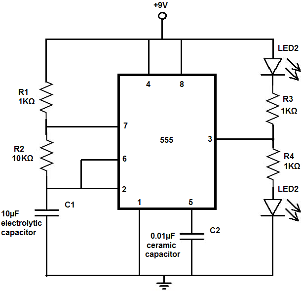
We can slightly modify the circuit above so that it flashes 2 LEDs.
The LEDs will flash alternatively. As one flashes on, the other flashes off.
This happens pretty quickly but it still can be seen with the human eye.
Additional Parts
- 1KΩ Resistor
- Red LED
We need all the parts listed for the first circuit, now with the addition of 1 more 1KΩ resistor and 1 red LED.
Circuit
The schematic diagram of the 2 flashing alternative LEDs is shown below:

Again, this will create a circuit where 2 LEDs now flash, alternative, like police sirens rotating between a blue siren and a red siren.
And this is how LED flasher circuits can be built with 555 timers.
To see a project of an LED flasher being built with an arduino board, see
Arduino LED Flasher Circuit. This same flasher can easily be built with a microcontroller like arduino.
Related Resources
How to Vary the Brightness of an LED
How to Build an LED Driver Circuit
How to Build a Dark-activated Light Circuit
