How to Build a Voltage-Controlled Oscillator (VCO) Circuit with a 4046 Chip
In this project, we will build a voltage-controlled oscillator (VCO) using a 4046 chip.
A voltage-controlled oscillator is an oscillator whose oscillation frequency is controlled by an input voltage.
Basically, the voltage input into the VCO chip controls how many times a digital signal will oscillate in a given time period.
The chip we will use is a 4046 chip. This is phase-locked loop IC. We will use the VCO portion of it to create our voltage-controlled oscillator circuit.
The voltage-controlled oscillator, as its output, produces digital signals that can
function as clock signals. The output are
digital values that oscillate repeatedly between 0 and 1, so that its value is 0-1-0-1-0-1...so on. This signal,
in turn, can be input into a
chip that needs a clock signal to function. This is one important and commonly used way of using a
voltage-controlled oscillator (VCO).
Components Needed
- 4046 Phase-locked loop IC
- 10MΩ resistor
- 220K1 resistor
- 1µF electrolytic capacitor
- 0.1µF film or disk capacitor
- 1N4001 power diode
- 1N4001 power diode
- 1N4733 5.1V zener diode
- Pushbutton (Normally Open)
The 4046 chip is a phase-locked loop. A phase locked loop IC consists of a voltage-controlled oscillator (VCO) and a phase detector. In this circuit, we will use only the VCO portion of the 4046 IC and not the phase detector. We use the chip just to generate a digital signal that can be used a clock signal.
The 4046 chip can be obtained very inexpensively (under $0.50) and it's available from a number of different online retailers. One place to find is at Tayda Electronics at the following link: 4046 Phase Locked Loop IC.
The 4046 is a 16-pin chip.
The pinout for the 4046 is shown below.
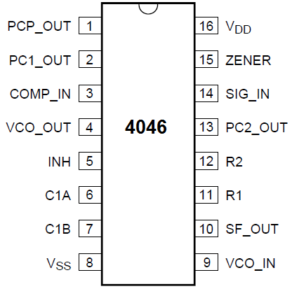
Pins 1, 2, 10, 12, 13, 14, and 15 are not needed for to produce a voltage-controlled oscillator.
We will use a variety of resistors and capacitors to form RC networks that determine factors such as the rate of the voltage drain and the maximum oscillation. This you will all see in the circuit schematic below.
The zener diode acts as a voltage regulator, setting the voltage at 5.1V. across it, for voltage input into pin 4. This is the voltage that controls the number of oscillations for the output digital signal of the chip.
A pushbutton is used to activate the the 4046 chip.
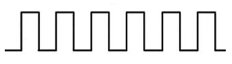
The oscillator will produce a digital square waveform such as that shown below.
Voltage-Controlled Oscillator (VCO) Circuit
The schematic diagram of the voltage-controlled oscillator we will build is shown below.
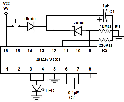
The circuit functions off of 9V of power.
The 4046 chip is a voltage-controlled oscillator and phase comparator IC. The 4046 is a dual purpose chip. It has 2 major processors that can be used independently of each other. For our purposes, we will use the 4046's VCO ability to convert analog voltage input to digital frequency output.
Analog input to the VCO is at pin 9.
Digital output of a square wave is at pin 4.
The first diode is used as a protective diode to prevent current from flowing back into the power supply.
The zener diode sets the voltage which is input into pin 9 of the 4046. The VCO in the 4046 compares the input voltage at pin 9 to the supply voltage at pin 16. There is a direct relation between the input voltage and the speed of oscillation at pin 4, the output. The higher the input voltage, the faster the oscillation ouput. The voltage input at pin 9 determines the frequency output at pin 4. The maximum oscillation is controlled by R2 and C2 (R2C2).
The rate of the voltage drain is controlled by the value of R1 and C1 (R1C1). The length of the rolldown is controlled by R1C1. The output starts quickly but "rolls down" to a complete stop.
An resistor and capacitor (RC) network can be connected between pins 12 and 6 of the 4046 chip. This RC network sets the minimum frequency of the digital oscillations. This is the frequency that the digital signal will have at its slowest oscillation value during any time of its oscillations. In our circuit, pin 12 is left unconnected, so the resistance is infinite. Thus, the minimum flash rate is 0 (full stop). As you will see below, this is why the LED flashing will come to a complete halt.
The circuit works like this. When you press down on the pushbutton and then release it, the LED turns on. With time, the LED
appears to be flashing, but so fast, you're not sure. As you patiently watch, the flashing becomes very obvious as it slows down. It should
slow down a crawl before it stops. It could stop with the LED on or off. But it will stop.
Related Resources
How to Build an Arduino Light Detector Circuit
How to Build a Night Light Circuit with a NAND Gate Chip
How to Build a NAND Gate Logic Circuit Using a 4011 Chip
How to Build a Touch Sensor Circuit with a NAND Gate Chip