How to Build a Light Detector Circuit Using an Arduino
In this project, we will go over how to build a light detector circuit using an arduino.
A light detector circuit is a circuit which can detect the presence or absence of light, depending on how we write our code to respond to the varying light levels. For example, if there is a great deal of light shining on our circuit, we can make anything that we want occur, such as have an LED light up. And we can do the same thing if there is a very low amount of light shining on our circuit. We could also just detect changes in light levels. We can detect a change when something passes in front of a light source, blocking the normal light to our circuit, etc.
For this circuit, we will make an LED light if there is a great amount of light hitting our circuit.
In another circuit, we will write a program for an LED to light when there is a very low amount of light, stimulating a night light.
For this project, the main component we will use is a photoresistor. When we place a photoresistor in series with a resistor, a voltage divider is formed. Voltage will be allocated to the 2 components based on the each one's respective resistance. More voltage will fall across the component with the greater resistance, according to ohm's law, V=IR. We will exploit this principle in this circuit to determine the light level that our circuit is exposed to.
Components Needed for the Light Detector Circuit
- Photoresistor
- 10KΩ Resistor
- Arduino
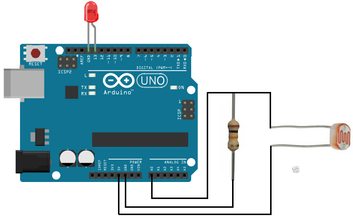
Light Detector Circuit Schematic
The schematic for the light detector circuit is shown below:
Code
The code to turn on an LED when sound is detected is shown below.
const int ledPin=13;
const int sensorPin= 0;
int level;
const int threshold=800;
void setup() {
pinMode (ledPin, OUTPUT);
pinMode (sensorPin, INPUT);
Serial.begin(9600);
}
void loop(){
level= analogRead(sensorPin);
if (level > threshold){
digitalWrite(ledPin, HIGH);
delay(50);
digitalWrite(ledPin, LOW);
}
else{
digitalWrite(ledPin, LOW);
}
}
Here in this code, we first define the pin connections. Since the LED is connected to digital pin D13, we set the pin to 13. Since the sensorPin representing the photoresistor voltage divider is connected to analog pin A0, we set it equal to 0.
Next, we declare an integer named level. This will represent the light level of our circuit, meaning how much light the circuit is exposed to. We also declare a variable named threshold and set it equal to 800. We later have code that if the circuit's light level is greater than the threshold level, the LED will turn on.
The next line declares the ledPin as a digital output.
After this, the next block of code reads the value from the analog pin A0. If the light level is above the threshold, the LED will light up.
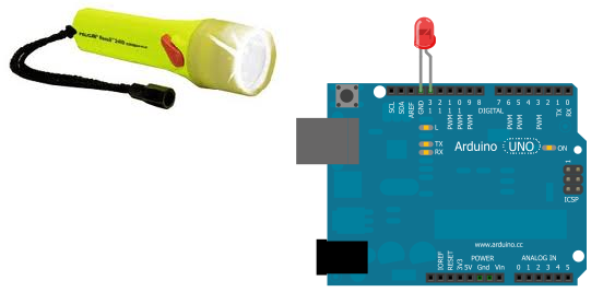
The biggest part of this circuit is knowing how the voltage divider circuit works. The voltage divider is again formed between the photoresistor and the 10KΩ resistor, and it is the heart of the circuit. The 5 volts feeding the voltage divider gets divided up and allocated to these 2 components based on their resistance values. When the photoresistor is exposed to very bright light such as when a flashlight is shined on it, its resistance becomes very low, 3KΩ or less. This means most of the voltage drops across the 10KΩ resistor and only a little drops across the photoresistor. Since the 10KΩ resistor is the part which is connected to the sensorPin, analog pin A0, the voltage across it is the reading of the sensor value. The analogRead() function reads the value of the voltage across the 10KΩ resistor and outputs a value range from 0 to 1024. If the voltage is low, it will output a value on the low end of this range. If the voltage across the 10KΩ resistor is high, it will output a value on the high end of this range. Again, when a bright light is shining on the photoresistor, its resistance is very low, typically 3KΩ or less. This means most of the voltage drops across the higher resistance element, the 10KΩ resistor. Thus, the sensor reading will be very high when a bright light is shining on the photoresistor. If the level is above the threshold of 800, which will be in the case when a bright light is shining on it, the LED attached to digital pin 13 of the arduino will light up. And this is how our circuit works.
When exposed to room light, the photoresistor will typically have a resistance of about 30KΩ. Thus, most of the voltage will fall across the photoresistor but a good amount will fall across the 10KΩ resistor. This typically leads to a sensor reading in the 500s range. This will not trigger the LED to turn on since the threshold level is 800.
In the last scenario, in total darkness, the photoresistor will have tremendously high resistane, in the megohms range. Thus, almost all of the 5V will fall across it and very little across the 10KΩ resistor. Thus, the sensor reading will be extremely small, typically less than 100. The LED will not light up.
And this is how an arduino can act as a light detector circuit.
To how this circuit actually works in real life visually, see the video below:
Related Resources
How to Drive a 7 Segment LED Display with an Arduno
How to Build a Dark-activated Light Circuit
How to Build a Hall Effect Sensor Circuit
How to Build a Touch Sensor Circuit
How to Build an Accelerometer Circuit
How to Build a Motion Detector Circuit
How to Build a Motion Detector Alarm Circuit