
How to Build a Multivibrator Circuit with a 4047 Chip
In this circuit, we will show how to build a multivibrator circuit to create digital square wave signals using a 4047 chip.
To create digital square waves, the 4047 needs to be in astable mode. In astable mode, the waveform signal is constantly fluctuating between HIGH and LOW, repeatedly. This is why it's called astable mode. It doesn't have a single stable output but constantly fluctuates back and forth between HIGH and LOW values. Being that it does this, it mimics a digital square wave signal.
This can be useful for many things, including acting as a clock signal for many different ICs which need clocks signals in order to operate. Many different ICs do including some counters, microcontrollers, digital potentiometers, and so on.
The frequency of the output waveform can be configured by an external resistor and capacitor. This will be explained in full detail below. But you can create many different varying frequencies with the 4047. So the 4047 can function as a variable digital square waveform oscillator.
The duty cycle, which is the period of time that the signal is HIGH for a given cycle, cannot be adjusted, though,
on the 4047. It has a duty cycle of 50% or very close to it. And that can't change. So if you need variable duty cycles,
the 4047 is not the chip to work with in that case.
Components
- 4047 Multivibrator Chip
- 10KΩ resistor
- 10μF capacitor
- Green LED
- Red LED
- Yellow LED
- 470Ω resistors
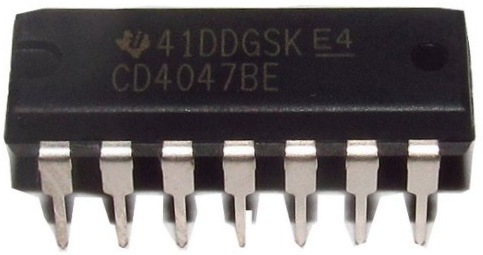
The 4047 multivibrator chip can be obtained for a couple of cents at various online electronic retailers. One place to get is at Tayda Electronics at the following link: TaydaElectronics- 4047 Multivibrator Chip.
The 4047 multivibrator is a 14-pin chip.
The datasheet for it can be found at the following link: 4047 Multivibrator Datasheet.
The pinout of the 4047 multivibrator is shown below.
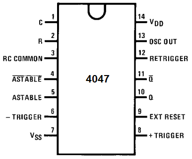
First, to establish power to the 4047 chip, we feed 5V to VDD, pin 14 and we connect VSS, pin 7 , to ground. The 4047 can actually work on an operating voltage of 3V-15V.
Pin 1 is where we place the external capacitor that is needed for the chip to create an output signal of a certain frequency.
Pin 2 is where we place the external resistor that is needed for the chip to create an output signal of a certain frequency.
Pin 3 is the RC common pin. This is the pin where the negative or cathode end of the resistor and capacitor connect to. You can see this in the schematic diagram below.
Pin 4 is the
Pin 5 is the ASTABLE pin.
In order for astable mode to be activated, either pin 4, the
Pin 6 is the - trigger pin.
Pin 8 is the + trigger pin.
The trigger pins are used for monostable mode operation. Monostable operation is obtained when the device is triggered by LOW-to-HIGH transition at the + trigger input or HIGH-to-LOW transition at the - trigger input.
Pin 9 is the external reset pin. A HIGH level on the reset input resets the outputs Q to LOW and
Pin 10 is the Q output pin.
Pin 11 is the
Pin 12 is the Retrigger Pin. Once the monostable operation is triggered on, to retrigger it, a simultaneous LOW-to-HIGH signal must be sent to both the + trigger and retrigger inputs.
Pin 13 is the Oscillator Out pin.
In actuality, there are 3 outputs on the 4047 that produce an oscillated output signal. There is the Osc Out
pin, the Q output pin and the
The Osc Out pin produces a frequency twice as fast as that of the Q and
Below is how the waveforms look for the 3 output pins in astable mode.
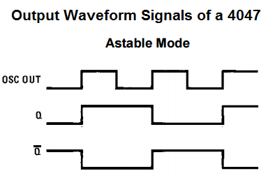
So now you can visually see that the Osc Out has a frequency twice that of the Q or
The Q and
The frequency of the output signal from Osc Out is twice that of Q or
Therefore, the frequency of the signal from Osc Out is, frequency= 1/4.4RC, where R is the value of the resistor and C is the value of the capacitor.
The frequency of the signal from Q and
4047 Astable Mode Multivibrator Circuit
The multivibrator circuit in astable mode we will build is shown below.
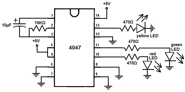
This 4047 multivibrator circuit is in astable mode.
To power the circuit, we feed anywhere from 3V-15V into VDD, which is pin 14. In this circuit, 5V is sufficient for turning on LEDs. But if you have a load which needs greater power, then you would need more voltage. We then connect the VSS pin to ground. These 2 connections establish sufficient power to the 4047 chip.
We tie both the ASTABLE and
Since we are not using monostable mode in this case, we really don't have any use for the - trigger, + trigger, or retrigger pin connections. So we simply tie them all down to ground.
We also do not use external reset because we're using astable mode, which is supposed to constantly fluctuate between HIGH and LOW. Therefore, we tie the external reset pin to ground.
To each of the output pins, we connect an LED along with a current-limiting resistor so that the LED doesn't burn out. You can place a different color LED to the 3 output pins so that it's more distinguishable which is which.
So when you turn on the circuit and it's up and running, you should see that the Q and
And this is how a multivibrator circuit can be built with a 4047 chip.
Related Resources
How to Vary the Brightness of an LED
How to Build an LED Driver Circuit
How to Build an LED Flasher Circuit