
How to Build a 4516 Binary Up/Down Counter Circuit
In this circuit, we will build a binary up/down counter with a 4516 chip.
A binary up/down counter chip is a chip which can count up or down in binary values incrementing or decrementing by 1 at a time.
So when the binary counter is in count up mode, it counts up from 0 to 1 to 2 to 3...all the way to 15, in binary values. After it reaches 15, it then goes to 0, starting all over again.
When the binary counter is count down mode, it counts in reverse. So if it's at 15, it then goes to 14, then 13, then 12, all the way down to 0. It then goes back to 15 and counts back to 0. And the cycle goes on and on.
A binary counter counts in binary. The 4516 chip has 4 data inputs. So it counts from 0000 to 1111 in count up mode. And from 1111 to 0000 in count down mode.
In this circuit, we will use a binary counter and connect it to a 4511 BCD to 7 segment display decoder. Since the binary counter increments by 1 each clock cycle in count up mode, we will see the decimal digit on the 7 segment display count up each cycle. So it'll initially display 0, then 1, 2, 3, 4, 5, 6, 7, 8, and then 9. It cannot display a digit above the value of 9. We can then switch to count down mode, and it will display 9, then 8, then 7, 6, 5, 4, 3, 2, 1, 0.
So this circuit uses a binary counter to display the decimal digits in sequential order, each up or down. It shows the practical use of binary counters and it enables you to count
up or down without having to use a microcontroller. So we can just use basic chips to count sequentially and physically show the results through a 7 segment LED display. It saves us to have
to connect to computers and have to write a program. So it's very useful.
Components
- 4516 Binary Up/Down Counter IC
- 4511 BCD to 7 Segment Display Decoder IC
- 7 segment display
- 7 470Ω resistors
- 4 1KΩ resistors
- Pushbutton
- Clock Signal Generator
The 4516 binary up/down counter can be gotten very cheaply for about $0.50 on ebay.
The 4516 is a 16-pin chip. The pinout of the 4516 is shown below.
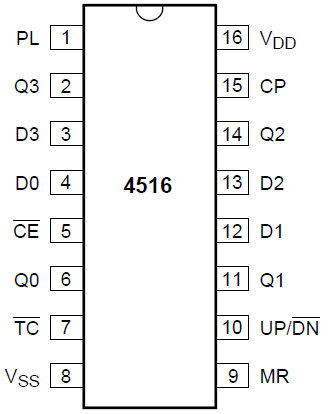
To power the chip, VDD, pin 16 to 5V and VSS, pin 8, connects to ground. The 4516 chip is capable of handling up to 18V.
Pin 1 is the preload pin. In normal operation, this pin is kept LOW or grounded. When HIGH, the chip functions in parallel load input.
D3, D2, D1, and D0, pins 3, 13, 12, and 4, are the data input pins.
B8, B4, B2, and B1 are the output pins. These are the pins we connect to the data input pins of the 4511 chip.
Pin 5 is the
Pin 7 is the
Pin 9 is the MR or Reset pin. It resets the count back to 0000. This pin is active HIGH. So in normal operation, it is connected LOW for the count operation to proceed. When connected HIGH, the output pins, Q0 to Q3, get reset to 0000.
Pin 10 is the Up/
Pin 15 is the clock pin. The 4516 chip is a chip that works on the clock signal. For each clock signal
input, the chip counts up or down by 1. Without a clock signal, the chip cannot work, so we must feed a clock signal
into pin 15.
4516 Binary Up/Down Counter Circuit
The binary up/down counter circuit we will build with a 4516 chip is shown below.
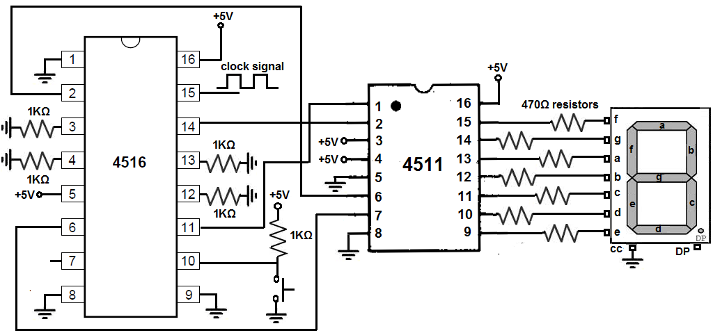
First, we power each of the chips. We do this by providing VDD with +5V to the 4511 and 4516 chips. The VDD pin is pin 16 for both chips. Then we connect VSS to ground on both chips. VSS is pin 8 for both chips.
For the 4511 is a BCD to 7 segment display decoder chip. It takes a binary value and displays the equivalent decimal digit on a 7 segment display. We're not going into great depth about connecting it. If you would like to see an in-depth circuit on how to connect the 4511, see 4511 BCD to 7 Segment Display Decoder Circuit.
But for a quick overview to connecting it here, we connect pin 3, the
Now for the 4516 binary up/down counter chip, we connect the preload pin to ground for normal counting operation.
We connect the
Pin 7 is the
We connect the MR pin, pin 9, to ground to disable the clearing feature of all outputs. If connected HIGH, all outputs would go to a LOW state.
We connect the Up/
The CP pin, pin 15, the clock pin. This pin needs a constant clock pulse in order for the circuit to work. The 4516 chip works on a clock signal. For each clock signal, it either increases or decreases the count by 1, depending on whether the chip is in up or down count mode. This clock signal can be given in a variety of ways. It can given with a 4046 VCO chip output. It can given from the output of a 555 timer in bistable mode. If you have function generator, you can also connect it to the pin and put a fairly low frequency signal into the clock. The generator should be put in square wave mode. You can calculate the time each cycle will take by taking the frequency and plugging it into the formula, T= 1/f, where T is the period in unit seconds and f is the frequency of the signal. You want a faily low signal, such as 1 Hz. 1Hz produces a time period of 1 second. So each clock cycle would 1 second. So you can actually see the output. Otherwise, the display would change so fast, you would barely be able to catch anything. So there's many ways of doing this.
D3, D2, D1, and D0 are the data input pins for the 4516 chip. They connect to ground through a resistor. We use a 1KΩ resistor for each of the data pins. When the circuit first starts out, it starts at 0000 for the value of the data pins and then counts up or down depending on the mode. So these data inputs need no data for us to enter it. It just automatically does so. There are some binary counters that allow presettable data inputs, but the 4516 does not.
The output pins, Q3, Q2, Q1, and Q0, connect to the data input pins of the 4511 chip. So that as the value
is incremented or decremented by 1 each clock cycle, the new data is input into the 4511 chip, which then displays it
on the 7 segment LED display. So the 4516 gives the data counting up or down by 1 each cycle and then feeds that
data into the 4511 chip, which then displays it on the 7 segment LED display.
So this is how a binary up/down counter with a 4516 chip works.
Related Resources
How to Vary the Brightness of an LED
How to Build an LED Driver Circuit
How to Build an LED Flasher Circuit