
How to Build a Delay Before Turn Off Circuit with a 555 Timer
In this circuit, we will show how to build a delay before turn off circuit with a 555 timer chip.
A delay before turn off circuit is a circuit that once you apply power to it turns on the output right away. The output stays on for a few seconds and then turns off. There is a delay before the output turns off.
A delay before turn off circuit can be useful for any circuit that needs to be on only for a short period of time, such as a timer. Say you want a circuit to only be on for 10 seconds and then stop. Then this circuit has perfect application.
How we achieve the delay effect is through the use of a capacitor. Basically the capacitor takes time to charge up. This time is what creates
the delay.
Components Needed
- 555 Timer Chip
- 47KΩ resistor
- 100μF capacitor
- 470Ω resistor
- LED
The 555 timer can be obtained very cheaply from pretty much any electronic retailer.
The 555 timer is an 8-pin chip.
The pinout of the 555 timer is shown below.
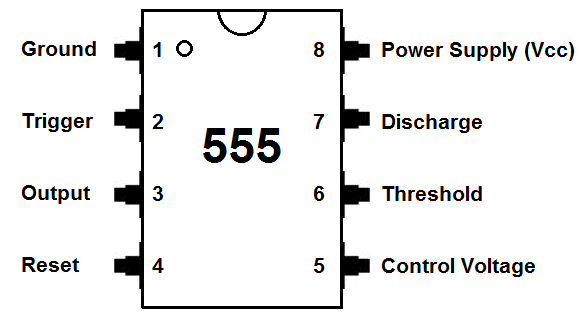
The 555 timer requires a power supply voltage of 4.5-16V. We connect this voltage to the VCC pin, pin 8, and we connect GND, pin 1, to ground.
The only other pins we use are the trigger pin, the output pin, the reset pin, and the threshold pin.
Pin 2 is the trigger pin. It works like a starter pistol to start the 555 timer running. The trigger is an active low trigger, which means that the timer starts when voltage on pin 2 drops to below 1/3 of the supply voltage. When the 555 is triggered via pin 2, the ouptut on pin 3 goes high.
Pin 3 is the output pin. 555 timer's output is digital in nature. It is either high or low. The output is either low, which is very close to 0V, or high, which is close to the supply voltage that's placed on pin 8. The output pin is where you would connect the load that you want the 555 timer to power. This may be an LED, for instance.
Pin 4 is the reset pin. This pin can be used to restart the 555 timer's timing operation. This is an active low input, just like the trigger input. Thus, pin 4 must be connected to the supply voltage of the 555 timer to operate. If it is momentarily grounded, the 555 timer's operation is interrupted and won't start again until it's triggered again via pin 2.
Pin 6 is the threshold pin. The purpose of this pin is to monitor the voltage across the capacitor that's discharged by pin 7. When this voltage reaches 2/3 of the supply voltage (VCC), the timing cycle ends, and the output on pin 3 goes low.
If you want to know all the pinout of the 555 timer in full depth, what each pin is and what each pin does, see 555 Timer Pinout.
In this circuit, we will connect the 555 timer to produce an on delay before the output goes LOW.
The connections are shown below.
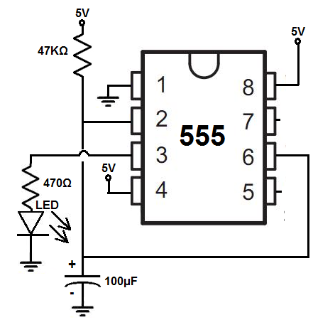
555 Timer Delay Before Turn Off Circuit
The 555 timer delay before turn off circuit we will build is shown below.
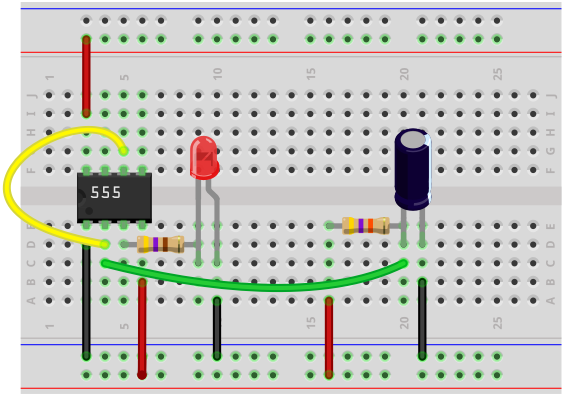
The breadboard schematic of the above circuit is shown below.
To connect power to the 555 timer chip, we connect about 5-15V to VCC, pin 8, and we connect pin 1 to ground.
We connect a 47KΩ resistor to the positive voltage supply and then to pin 2. We connect pin 6 to pin 2 and then connect a 100μF capacitor to ground.
We connect pin 4, the reset pin, to the VCC. The reset pin is active low. So in order for reset not to be triggered, we connect this pin permanently HIGH.
Pin 3 is the output pin. Therefore, we connect the LED along with the 470Ω resistor to ground to protect the LED from excess current.
How the Circuit Works
How this circuit works is through the RC network. The combination of the resistor and capacitor forms the RC network. This network determines the length of time it takes to charge the capacitor.
The reason why the circuit turns on automatically is because pin 6, the threshold pin, is initially LOW. When pin 6, the threshold pin, is LOW, the output is HIGH. That's why the LED is on. This pin represents the voltage across the capacitor. Initially, because it takes time for a capacitor to charge up, it's going to have very low voltage initially until it builds up voltage. Once a few seconds pass by, the capacitor is able to charge up. As it charges up to greater than 2/3 of the supply voltage, then the output goes LOW. This is why the LED eventually shuts off. It's when the capacitor charges to 2/3 of the supply voltage. Once the threshold reaches this voltage, then the pin is HIGH. So the output goes LOW and the LED turns off.
There is a delay of about 5 seconds with this circuit. once you turn the power on, the LED stays on for about 5 seconds and then permanently shuts off.
The RC network is what determines this delay time. The bigger the resistor and capacitor value, the longer the delay. So if you want to increase the time of the delay, you would choose a bigger resistor and capacitor. If you want to shorten the time of the delay, you would choose a smaller resistor and capacitor value.
And this is how a delay before turn off circuit works with a 555 timer.
To see how this circuit works in real life, see the video below.
Related Resources
How to Build a Delay Before Turn On Circuit with a 555 Timer