
555 Timer Pinout
We will go over the pinout of the 555 timer.
The 555 timer is an 8-pin IC.
This means it has 8 different pins, each of which have different functions for the IC.
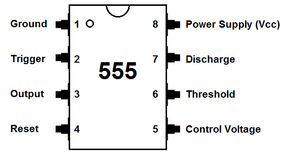
The chart below gives the identities of each of the pins and what function they play in a circuit.
| Pin Number | Pin Name | Pin Function |
| 1 | Ground | Pin 1 connects the 555 timer chip to ground. |
| 2 | Trigger | Pin 2 is the trigger pin. It works like a starter pistol to start the 555 timer running. The trigger is an active low trigger, which means that the timer starts when voltage on pin 2 drops to below 1/3 of the supply voltage. When the 555 is triggered via pin 2, the output on pin 3 goes high. |
| 3 | Output | Pin
3 is the output pin. 555 timer's output is digital in nature. It is
either high or low. The output is either low, which is very close to
0V, or high, which is close to the supply voltage that's placed on pin
8. The output pin is where you would connect the load that you want the 555 timer to power. This may be an LED, in the case of a 555 timer LED flasher circuit. |
| 4 | Reset | Pin
4 is the reset pin. This pin can be used to restart the 555 timer's
timing operation. This is an active low input, just like the trigger input. Thus, pin 4 must be connected to the supply voltage of the 555 timer to operate. If it is momentarily grounded, the 555 timer's operation is interrupted and won't start again until it's triggered again via pin 2. |
| 5 | Control Voltage | Pin
5 is the control pin. In most 555 timer circuits, this pin is simply
connected to ground, usually through a small capacitor, about 0.01
µF capacitor. This capacitor serves to level out any fluctuations in
the power supply voltage that might affect the operation of the timer. Some circuits (though rare) do use a resistor between the control pin and Vcc to apply a small voltage to pin 5. This voltage alters the threshold voltage, which in turn changes the timing interval. Most circuits do not use this capability, though. |
| 6 | Threshold | Pin 6 is the threshold pin. The purpose of this pin is to monitor the voltage across the capacitor that's discharged by pin 7. When this voltage reaches 2/3 of the supply voltage (Vcc), the timing cycle ends, and the output on pin 3 goes low. |
| 7 | Discharge | Pin 7 is the discharge pin. This pin is used to discharge an external capacitor that works in conjunction with a resistor to control the timing interval. In most circuits, pin 7 is connected to the supply voltage through a resistor and to ground through a capacitor. |
| 8 | Power Supply (Vcc) | Pin
8 is connected to the positive power supply voltage. 555 timer ICs need DC voltage in order to operate. This is the pin which connects to the DC voltage to power the 555 chip. The voltage must be at least 4.5V and no greater than 15V. It's common to run 555 timer circuits using 4 AA or AAA batteries for 6V or a single 9V battery. |
Connecting the pins in different ways, we can put the 555 timer in astable mode, bistable mode, or monostable mode.
The 555 timer can be used for basic timing functions, create warning lights that flash on and off, produce musical notes of varying frequencies, and even control
the control position of a servo motor.
To see a project where we create a LED flasher circuit with a 555 timer, see LED flasher circuit.
HTML Comment Box is loading comments...