
How to Build an Oscillator with a 7414 Schmitt Trigger Inverter Chip
In this circuit, we will show how we can build an oscillator circuit with a 7414 schmitt trigger inverter chip.
The only 2 components that we have to add externally to the 7414 chip is a resistor and a capacitor in parallel.
The oscillator will produce digital square wave signals of a 50% duty cycle. A digital square wave is a wave form that alternates between on and off, on and off, repeatedly. a 50% duty cycle means that the on and off periods are of equal duration. For a given cycle, the square wave is on or HIGH 50% of the time and off or LOW the other 50% of the time.
An oscillator circuit is important and can have many uses in many different circuits and devices. Oscillators can be used for the clock signals which many different chips need to operate. These include counter chips, digital potentiometer chips, and many different types of microprocessors. The clock signals provides a way that a master and slave device can act in synchrony with each other. Either on the falling or rising edge of a clock signal, the 2 devices will work in synchrony so that they can produce a desired outcome.
Besides acting as a clock signal, oscillators can function to flash or blink a device. If you feed the output of an oscillator into an output device such as an LED, the LED will flash on and off at the rate of the frequency of the output signal. Oscillators can also function as a PWM signal. By varying the frequency of the output signal or the duty cycle of the signal, we can simulate a pulse width modulated signal. These can be used, for example, to control motors. By varying the frequency and the duty cycle, we can control motor speed.
There are many different uses.
So we'll now go to building the circuit below.
Components Needed
- 7414 Schmitt Trigger Inverter
- 100KΩ resistor
- 10μF capacitor
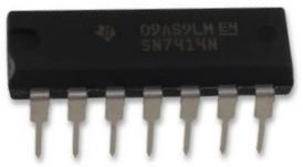
The 7414 hex inveter gate chip can be obtained very cheaply from a number of online retailers for just a few cents. One place it can be obtained from is Tayda Electronics at the following link: Tayda Electronics- 7414 Hex Inverter Gate IC. However, it is a very popular chip and many electronics parts suppliers have them.
The pinout of the 7414 is shown below, so that you can see how to
connect it in the circuit.
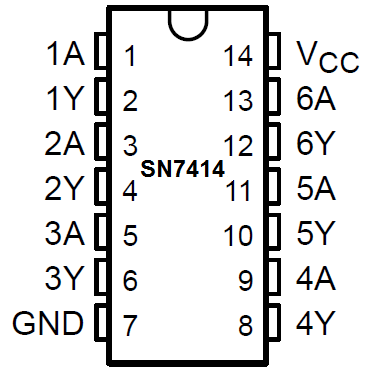
This inverter has 6 independent inverter gates.
The pins marked with A's are the inputs to the inverter gates and the pins marked with Y's are the outputs of the inverter gates.
In this circuit, we will simply be using one gate.
The 74c14 either outputs a HIGH or a LOW, as all logic chips.
The output is LOW when the input is above 66% of the supply voltage. So if we're feeding the 10V, the output is LOW when the voltage rises above 6.6V. Since it's an inverter chip, 6.6V or higher produces a LOW output signal.
The output is HIGH when the input is below 33% of the supply voltage. So, again, if we're feeding the chip 10V as the supply voltage, the output will be HIGH if an input between under 3.3V.
In between 33% and 66% of the supply voltage is a gray area. As we just said above, when the input voltage is above 66% of supply voltage, the output is LOW. And when the input voltage is below 33% of the supply voltage, the output is HIGH. In between these values is the gray area between 33% and 66%. This is called the hysteresis gap. This gap exists on purpose and was created by engineers so that the chip does not change the output due to small fluctuations in voltage. If the input voltage is above 66% of the supply voltage, which makes the output LOW, in order for the output to change to HIGH, the voltage has to fall below 33% of the supply voltage. If the input voltage is below 33%, which makes the output HIGH, the input voltage has to go above 66%, in order to change to a LOW output. The output will not change values between 33% and 66%. This allows room for small fluctuations in input voltage. Otherwise, the output would constantly be changing outputs for any tiny fluctuation in voltage, and this would be largely undesired.
The hysteresis gap was designed and exists for this reason.
So basically in this circuit, the charging and discharging of the capacitor creates the square wave signals. When the capacitor is charged (to greater than 66% of the supply voltage), the output goes LOW. When the capacitor discharges to below 33% of the supply voltage, the output goes HIGH.
The capacitor by itself does not create a square wave. It creates an irregular triangle-type waveform.
This diagram is shown below.
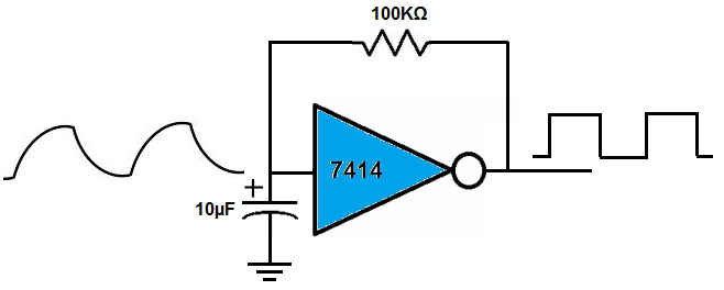
The capacitor charges up in down in waveforms seen on the left, which resembles a sawtooth or irregular shaped triangles. This is the waveform that is input into the 7414 schmitt trigger inverter. on the output side, we get a perfect digital signal waveform.
How does this occur?
Just think of how an inverter work. An inverter can only output a LOW or HIGH signal. When the signal being fed into the inverter is when the capacitor has discharged to less than 33%
of the supply voltage, the output signal of the inverter will be HIGH; this is during the whole time that the capacitor has discharged to less than 33% of the supply voltage. When the capacitor now has
charged up to 66% or greater of the supply voltage, the output signal of the inverter will be LOW. So this is how we get a pure digital signal from the inverter, with equal HIGH and LOW periods, so the duty
cycle is 50%.
7414 Oscillator Circuit
The oscillator circuit we will build with a 7414 schmitt trigger inverter chip to produce a 1Hz signal is shown below.
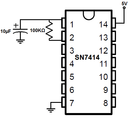
The breadboard schematic of the above circuit is shown below.
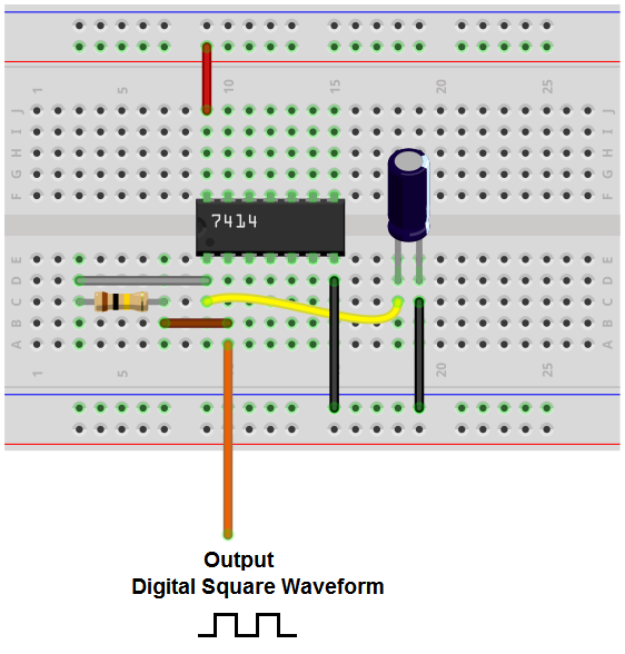
So in this circuit we have a 100KΩ and a 10μF.
The formula to calculate the frequency that the output signal will oscillate at is f= 1.2/R*C. Being that we want our output signal to oscillate at 1Hz, we use a 100KΩ resistor and a 10μF capacitor. Plugging these values into the formula gives f= 1.2/(100KΩ * 10μF)= 1.2Hz, which is obviously close enough to 1Hz.
When we want to really low-frequency signals, we use large values for the resistors and capacitors. This is because when we use large values for the resistors and capacitors, it takes a longer time for the capacitor to charge up and a longer time for the capacitor to discharge. This creates a longer time period for the signal, which results in a low frequency signal.
on the other hand, if you want a very high-frequency signal, you would use a small resistor and a small capacitor, such as a capacitor in the picofarads. When you have a capacitor in the picofarads, it can only hold a small amount of charge, so it charges up fast and discharges fast. Thus, the signal is high frequency,
And medium-frequency is obviously somewhere in the middle.
And this is how we can create an oscillator circuit that can create an output signal of any frequency.
To see how this circuit functions in real life, see the following video below.
Related Resources