
7414 Oscillator Calculator

The oscillator calculator built using a 7414 schmitt trigger chip calculates the frequency and time period of the digital square wave signal output by the 7414.
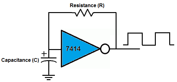
The 7414 schmitt trigger chip can act as an oscillator circuit, which can function for various uses in circuits in which oscillators are needed. It can function to allow devices to flash. For example, if you connected an LED (along with a current-limiting resistor) to pin 2 of the 7414, which is the output of the first gate of the 7414, it would flash repeatedly on and off. This is because a digital square wave is output at pin 2. The square wave has a duty cycle of 50%, which means that the time it is on and off are equal. This oscillator circuit can also function as a clock for a device.
How the frequency that the output signal of the 7414 will be is determined by an external capacitor and resistor in parallel with each other, according to the formula, frequency = 1.2/(resistance * capacitance).
So the greater the capacitance and resistance is, the shorter the frequency of the output signal. This is because if you use a big capacitance, it takes a longer time to charge up and a longer time to discharge. Being that it takes this amount of time, the frequency is much shorter than if it took a short period of time. If the time period is longer, the frequency is less. This is the same principle that applies to using a large resistance value. The greater the resistance, the more resistance there is to current flow. Thus, there is less current flow. So it takes the current a much longer time to travel. On the other hand, if you use a very small capacitor, it can charge up very quickly and discharge very quickly, because it doesn't hold much charge. Therefore, the time it takes to charge and discharge is less, so the frequency is greater.
The time period, T, we calculate is simply the inverse of the frequency. The formula is, T=1/f, where f is the frequency of the output signal.
As an example calculation, if we use a 100KΩ resistor and a 10μF capacitor, this will produce a frequency of, f= 1.2/(100KΩ * 10μF)= 1.2Hz, which is a time period of, T=1/f=1/(1.2)=
0.83s.
Related Resources
How to Build an Oscillator Circuit with a 7414 Schmitt Trigger Chip
Colpitts Oscillator Calculator
Hartley Oscillator Calculator
LC Resonance Calculator
Op Amp Oscillator Calculator