
AC Circuit Analysis- Time Domain to Frequency Domain Conversion
In this article, we will explain how to convert a circuit from the time domain to the frequency domain.
Converting a circuit from the time to the frequency domain is only done for AC circuits, since AC circuits are the only circuits in
which the power source has a frequency that is greater than 0 Hz.
In DC circuits, the frequency of the source is 0 Hz. Therefore, reactive components such as capacitors and inductors are neutral, so there would be no need to
analyze it in the frequency domain. Only with AC circuits (circuits that are powered by an AC power source) are circuits analyzed in the frequency domain.
A DC circuit is one that is powered by a DC voltage source such as a battery; DC circuits wouldn't warrant frequency analysis due to the fact that the frequency of the
power source is 0Hz, which creates no reactance (in reactive components).
Why Is it Necessary To Convert From the Time Domain to the Frequency Domain?
So why is this process done?
And the answer is very simple.
We do it when we want to analyze a circuit from a frequency perspective- how the frequency of the power source affects the circuit.
AC sources are different than DC sources.
While AC sources have a frequency greater than 0 Hz, DC sources have a frequency of 0 Hz. Reactive components behave one way in DC circuits and another way in AC (higher-frequency circuits). In other words, they react differently based on the frequency of the input power source.
Capacitors and inductors offer different impedances (resistances) depending on the frequency of the power source.
Therefore, with AC signals, many times we want to analyze the circuit from the frequency domain, to see how the frequency of the AC source impacts the circuit (by impacting the reactive components).
For example, to demonstrate how different they are, let's consider the case of an AC signal with a frequency of 60Hz vs an AC signal with a frequency of 1000Hz.
Let's take a capacitor, say a 100μF.
This capacitor is going to have a completely different response to the 60Hz power source and the 1000Hz power source.
With the 60Hz power source, the capacitor has a reactance of, ZC= -j/ωC= -j/(376.8 rad/s)(100μF)= -j26.
With the 1000Hz power source, the capacitor has a reactance of, ZC= -j/ωC= -j/(6280 rad/s)(100μF)= -j1.6.
Therefore, the capacitor, fed by the 60Hz source, has a much greater reactance than the capacitor powered by the 1KHz source.
So based on the frequency of the AC source determines the characteristics that the reactive components of the circuit will have.
This is why we must convert an AC circuit in the time domain to the frequency domain. In the frequency domain, the circuit reacts differently due to the nature of reactive components.
Now we'll go ahead and actually convert an AC circuit from the time to the frequency domain.
Converting a Circuit From the Time to the Frequency Domain
So the best way to understand how to do this is actually convert a circuit from the time domain to the frequency domain.
So we'll take the circuit below and convert it from the time domain to the frequency domain.
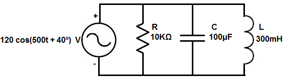
So we will show how to convert each of these values into their equivalent frequency component.
Resistors
We will start with the resistor, R, which is 10KΩ.
The resistor is the easiest component to convert because the value doesn't change.
A resistor is not a reactive component. It offers the same resistance regardless of the frequency of the power source feeding it.
Therefore, the resistor remains unchanged at 10KΩ in the frequency domain.
Capacitors
The next component we will focus on is the capacitor.
A capacitor is a reactive component. Therefore, the impedance it offers in a circuit changes based on the frequency of the power signal feeding it.
The formula to convert the capacitance from the time to the frequency domain is shown below.
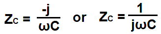
So the formula to convert a capacitance value from the time to the frequency domain is shown above.
Since it's the same power source, ω=500. We need this value to compute the reactance of the capacitor in the frequency domain.
So going back to the capacitance formula, we take it and plug in the capacitor value, 100μF, into the formula. Doing this we get, ZL= -j/ωC= j(500 rad/s)(100μF)= -j20.
The j value, again, represents the phase of the component.
Capacitors, in the frequency domain, will always have a negative j value.
A negative j value symbolizes that the voltage lags the current. Current goes through a capacitor before volage is formed across the capacitor. A negative j value is just an imaginary component that symbolizes this relationship between voltage and current.
So this is how capacitors can be converted to the frequency domain from the time domain.
Inductors
The next component we will focus on is the inductor.
An inductor, just like a capacitor, is a reactive component. Therefore, the impedance it offers in a circuit changes based on the frequency of the power signal feeding it.
The formula to convert the inductance from the time to the frequency domain is shown below.
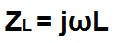
So the formula to convert an inductance value from the time to the frequency domain is shown above.
Since it's the same power source, ω=500. We need this again to compute the reactance of the inductor in the frequency domain.
So going back to the inductance formula, we take it and plug in the inductor value, 300mH, into the formula. Doing this we get, ZL= jωL= j(200 rad/s)(300mH)= j60.
The j value, again, represents the phase of the component.
Inductors, in the frequency domain, will always have a positive j value.
A positive j value symbolizes that the voltage leads the current. Voltage is built up across an inductor before current is allowed through. A positive j value is just an imaginary component that symbolizes this relationship between voltage and current.
So this is how inductors can be converted to the frequency domain from the time domain.
Power Source
The last component to convert to the frequency domain is the power source itself.
You can see that the representation, 120 cos(200t + 40º) V, represents the signal in the time domain. This is made obvious by the t in the formula.
However, this, too, must be changed to the frequency domain and how it is representated in the frequency domain is in phasor format.
Phasor form simply represents the amplitude of the signal and the phase. It doesn't take into account frequency because we've already computed the frequency into each of the components already. Therefore, it doesn't need to be emphasized again.
Therefore, the representation, 120 cos(200t + 40º) V, is equal in phasor form to 120<40º.
And this is everything required to convert components and a power source from the time to the frequency domain.
We're going to go through one more circuit and do a full analysis on it as could be done with a DC signal.
AC Circuit Time to Frequency Domain- Full Example
So the circuit we're going to full convert from the time domain to the frequency domain and analyze fully is shown below.
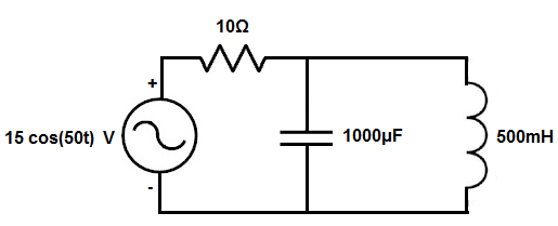
So the first thing is to individually convert all the values to the frequency domain.
The power source, 15 cos(50t) is represented in phase form by 15<0º.
All the resistors keep their same value.
The 1000μF capacitor is, ZC = -j/ωC= -j/(50)(1000μF)= -j20
The 500mH inductor is, ZL = jωL= j(50)(500mH)= j25.
These are all the conversions necessary.
This circuit is now shown below in the frequency domain.
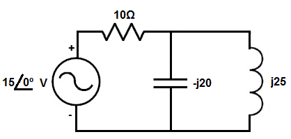
Now that the circuit is fully converted, we can analyze the circuit using common circuit analysis techniques, such as KCL or KVL.
This particular circuit lends well to KCL analysis, so that is how we will analyze it.
So if we look at first node after the power source, we know that current is flowing from the power source through the 10Ω resistor into the node. At that node, current flows from the node into the capacitor and from the node into the 500mH inductor.
So you just have to be consistent with your positive and negative symbols. We'll adopt the convention of current entering a node being positive and current leaving a node being negative.
So taking this into account, we get this mathematic result shown below.
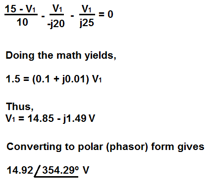
If you want, you can convert this voltage back into the time domain.
The polar form of 14.92<354.92º makes the voltage source 14.92 cos(50t + 354.92º) in the time domain.
So we used KCL to analyze this AC circuit in the frequency just like we would with a DC circuit.
This is how AC circuits can be analyzed in the frequency domain.
It's just a matter of first converting the circuit from the time domain to the frequency domain, and then doing the regular circuit analysis that you would normally do to solve the problem.
So it's basically a 2-step approach.
Related Resources
Time to Frequency Domain Converter for AC Circuits
What is the Nominal Value of a Component?
What is a Live Circuit?
Why does a Circuit Always Have to Have Ground?
What is the Admittance of a Circuit?
What is Impedance?
How to Increase Voltage in a Circuit
Source Transformation of Circuits
What is an Active Low Device?
What is an Active High Device?