
Time to Frequency Domain Converter for AC Circuits
This time to frequency domain converter connverts a circuit from the time domain to the frequency domain.
This time to frequency domain converter is applicable only to AC circuits, circuits which are powered by an AC power source. This circuit does not work or apply to DC circuits.
Components that offer different impedance (resistance) to AC power sources than DC power sources are reactive devices. Reactive devices are reactive, or changes, with the frequency of the power source powering the components.
Devices that are reactive are capacitors and inductors. Capacitors and inductors offer different impedances based on the frequency of the power source powering them.
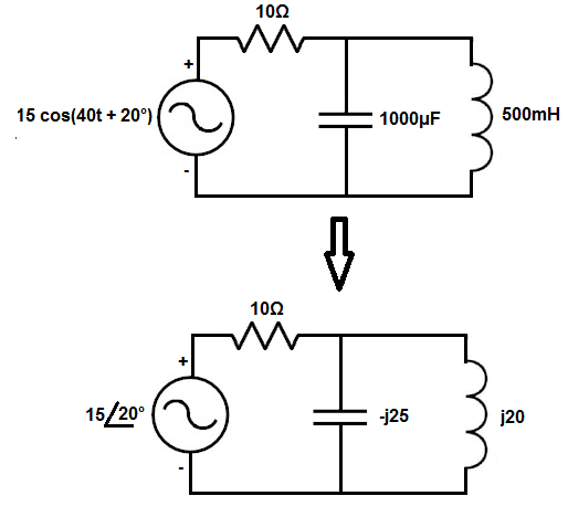
The formula to convert capacitance from the time to the frequency domain is ZC = 1/jωC. Another way to rewrite it is, ZC = -j/ωC. Both are the formula.
So if the angular frequency of the power source is 200 radians per second (rad/s) and the capacitor has a capacitance of 100μF, we then plug this value into the formula shown above and can compute the impedance the capacitor offers in the frequency domain. So going back to the capacitance formula, we take the values and plug it into the formula. Doing this we get, ZC= -j/ωC= -j/(200 rad/s)(100μF)= -j50.
The j value really represents the phase of the component.
Capacitors, in the frequency domain, will always have a negative j value.
A negative j value symbolizes that the voltage lags the current. Current is built up across a capacitor before voltage. A negative j value is just an imaginary component that symbolizes this relationship between voltage and current.
So this is how capacitors can be converted to the frequency domain from the time domain.
The formula to convert the inductance from the time to the frequency domain is, ZL = jωL.
So if the angular frequency of the power source is 1000 radians per second (rad/s) and the inductor has an inductance of 20mF, we then plug this value into the formula shown above and can compute the impedance the capacitor offers in the frequency domain. So going back to the inductance formula, we take the values and plug it into the formula. Doing this we get, ZL= jωL= j(1000 rad/s)(20mF)= j20.
The j value, again, represents the phase of the component.
Inductors, in the frequency domain, will always have a positive j value.
A positive j value symbolizes that the voltage leads the current. Voltage is built up across an inductor before current is allowed through. A positive j value is just an imaginary component that symbolizes this relationship between voltage and current.
So this is how inductors can be converted to the frequency domain from the time domain.
Resistors don't factor into this formula because resistors aren't reactive components. Resistors offer the same resistance in a circuit regardless of the frequency of the power source powering them.
The last thing this converter takes into account is the power source. It converts the power source from a time domain to the frequency domain.
Usually power sources in the time domain have a t somewhere in the expression for the power source, the t standing for time. This signifies that the power source is expressed in the time domain.
Examples of power sources in the time domain are 50 cos(60t + 30º), 12 cos(4t), and 15 sin (50t - 60º).
The first number before the sine or cosine functions are the amplitudes of the power sources. The amplitudes of the examples above are 50, 12, and 15, respectively.
The number before the t represents the angular frequency of the power source. The angular frequencies of the examples above are 60, 4, and 50, respectively.
The number after the plus (+) or minus (-) sign is the phase of the power source. The phases of the examples above are 30º, 0º, and -60º.
So all that what's talked about represents the power source in the time domain.
We want to convert this to the frequency domain. To convert the frequency domain, we change the power source to a phasor, or polar form.
In the phasor form, the power source only takes into account the amplitude of the power source and its phase. It doesn't take into account the frequency of the power source, because once we convert the components to the frequency domain, the frequency is already accounted for.
So, for example, the power source 10 cos(5t + 20º) in the time domain is 10<20º in the frequency domain.
One more thing that must be explained is that when a power source is expressed in the time domain, such as 9 sin(20t + 15º), 20 is represents the omega, the angular frequency of the power source. It doesn't represent the frequency in pure hertz. Normally, frequency is expressed in the time domain as omega(ω), the angular frequency, as would be found in the formula.
This converter can convert either the power source, inductance, or capacitance into its equivalent value in the frequency domain. If you simply want to convert the power source, just enter the power source in the time domain and calculate. When entering the power source, the formula x1 cos(x2 t + x3º), where x1, x2, and x3 are numbers. Parentheses and the variable, t, must be in the expression for the converter to work.
If converting a reactive component, the capacitor and inductor, the value of these components must be entered as well as the power source, because the frequency must be taken into account.
This converter is useful for AC circuit analysis.
Related Resources
AC Circuit Analysis- Time to Frequency Domain Conversion
Series and Parallel Capacitor Calculator
Capacitance Calculator
Capacitor Charge Calculator
Capacitor Current Calculator
Capacitor Voltage Calculator (from current)
Capacitor Voltage Calculator (from charge)
Capacitor Impedance Calculator
Capacitor Charging Calculator
Capacitor Discharge Calculator
Capacitor Energy Calculator
Capacitor Voltage Divider Calculator
Bypass Capacitor Calculator